Automatic assembly tool for tool handle

An automatic assembly and handle technology, applied in manufacturing tools, other manufacturing equipment/tools, metal processing, etc., can solve the problems of large space, high labor costs, time-consuming and labor-intensive, etc., to improve efficiency and yield, save labor costs and The effect of site costs

Active Publication Date: 2016-03-09
SHANGHAI XINYUE TOOLS
View PDF12 Cites 9 Cited by
  • Summary
  • Abstract
  • Description
  • Claims
  • Application Information

AI Technical Summary

Problems solved by technology

Not only does it require a larger site, but it also requires higher labor costs
At the same time, the requirements for workers at the second and third stations are higher, because once the workers at these two stations make a s

Method used


Image

  • Automatic assembly tool for tool handle
  • Automatic assembly tool for tool handle
  • Automatic assembly tool for tool handle

Examples


Embodiment Construction

[0032] In order to make the present invention more comprehensible, preferred embodiments are described in detail below with accompanying drawings.

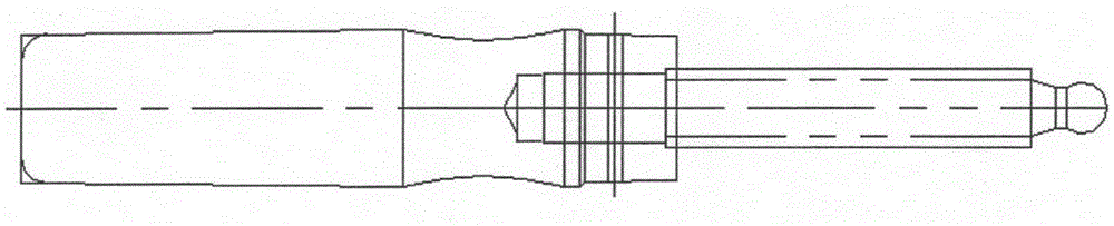
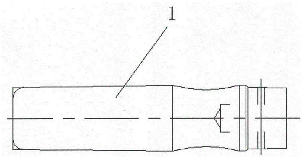
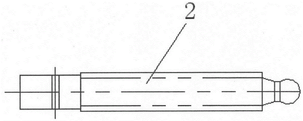
[0033] Such as image 3 As shown, the tool handle automatic assembly tool provided by the present invention is characterized in that it includes six clamps 4 for fixing the gripping part 1 and the connecting rod 2 . Such as Figure 5A and Figure 5B As shown, the fixture 4 includes a base plate 4-1, a V-shaped positioning block 4-2 is provided in the middle of the base plate 4-1, and a corner cylinder 4-3 is provided beside the V-shaped positioning block 4-2, and a Z-shaped pressing plate 4- One horizontal part of 4 is connected and fixed with the output shaft of the corner cylinder 4-3, and the other horizontal part of the Z-shaped pressing plate 4-4 presses and positions the connecting rod 2 in the V-shaped groove of the V-shaped positioning block 4-2, The front and rear sides of the V-shaped positioning block 4-2 are respect...


PUM


Abstract

The invention relates to an automatic assembly tool for a tool handle. The automatic assembly tool is characterized by comprising six clamps used for fixing a holding part and a connecting rod, six work stations distributed in the circumference direction, and a rotary disc rotating according to beats; a horizontal pressing mechanism and a reverse drilling rivet hole mechanism which are arranged on the second work station, a vertical drilling rivet hole mechanism arranged on the third work station, a rivet installing mechanism arranged on the fourth work station, a workpiece rotating mechanism arranged on the fifth work station, and an oil pressure rivet machine arranged on the sixth work station. According to the automatic assembly tool for the tool handle, a handle structural workpiece can be installed automatically, not only are the efficiency and the yield improved, but also the manpower cost and the site cost are reduced.

Description

technical field [0001] The invention relates to a tool capable of automatically completing handle assembly. Background technique [0002] Most tools have handles, a relatively common handle structure such as figure 1 As mentioned, it consists of Figure 2A Grip 1 shown and as Figure 2B The connecting rod 2 shown is assembled. At present, this kind of handle is mostly assembled manually, and the assembly process is as follows: the worker at the first station presses the connecting rod 2 into the grip part 1; The first rivet hole is punched on the grip part 1, and the rivet hole runs through the connecting rod 2 in the grip part 1 at the same time; the worker at the third station uses a punching machine to punch the second rivet hole on the grip part 1, The rivet hole runs through the connecting rod 2 in the grip part 1 at the same time; the workers at the fourth station penetrate the rivets in the two rivet holes; the workers at the fifth station use the rivet machine to...

Claims


Application Information

Patent Timeline
IPC IPC(8): B23P23/04B23P19/027
CPCB23P19/027B23P23/04
Inventor 赵蔚然
Owner SHANGHAI XINYUE TOOLS
Why Eureka
Try Eureka