Machine for detecting tiny particles

Inactive Publication Date: 2017-06-08
CHEN MING SHENG
View PDF5 Cites 0 Cited by
  • Summary
  • Abstract
  • Description
  • Claims
  • Application Information

AI Technical Summary

Benefits of technology

The present invention aims to provide a machine that can accurately and precisely measure the size and location of a small particle, which will improve the efficiency and yield of manufacturing a wafer. Additionally, the invention seeks to provide a machine that can quickly and comprehensively scan a mask.

Problems solved by technology

For example, when the optical module casts light on an upper face of the mask, which is made of a glass plate that is transparent, a pattern on a lower face of the mask jeopardizes the precision, effect and efficiency of inspection of tiny particles on the upper face of the mask.
However, such an optical module is expensive.
Furthermore, it is difficult to focus in such optical scanning because the mask is made of a perfectly plain transparent plate made of quartz or glass.
Moreover, it takes a lot of effort and time to precisely determine the size of a tiny particle because of a shadow on a lateral side of the tiny particle.
Hence, the size of tiny particles that can be determined with precision is limited to 50 um×50 um because of such shadow.
In addition, the width of wiring of an integrated circuit is getting smaller, and so is the size of tiny particles that must be found and removed from an integrated circuit.
Hence, such a modern optical is getting less satisfactory.
As discussed above, conventional methods or apparatuses for detecting tiny particles are limited regarding efficiency, effectiveness and precision.
It is not easy for a person to determine the size of a tiny particle with such conventional methods or apparatuses.
The efficiency and yield of related manufacturing of semiconductor are affected.

Method used


Image

  • Machine for detecting tiny particles
  • Machine for detecting tiny particles
  • Machine for detecting tiny particles

Examples


Embodiment Construction

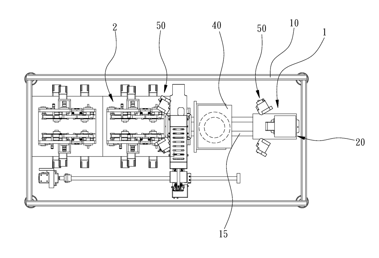
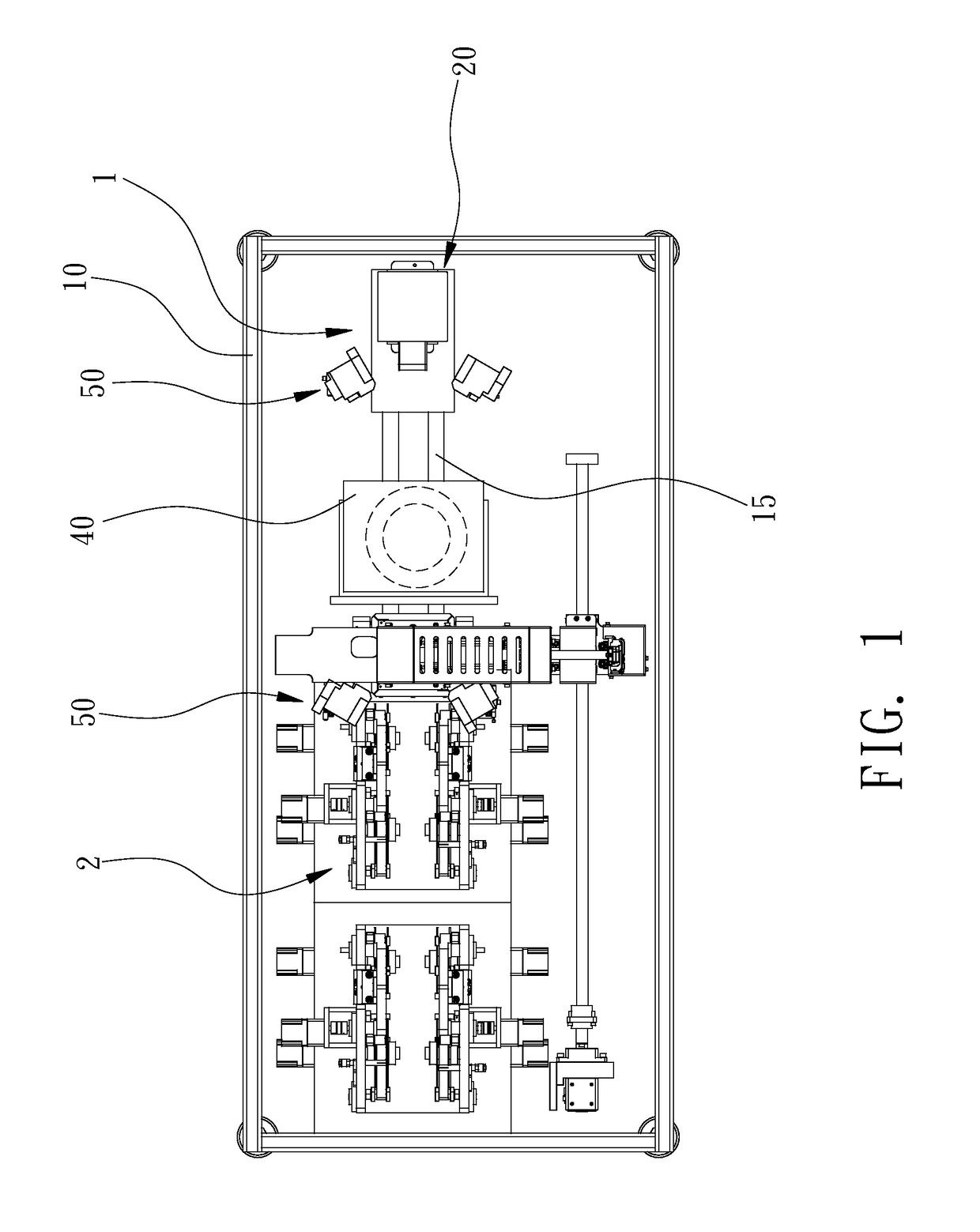
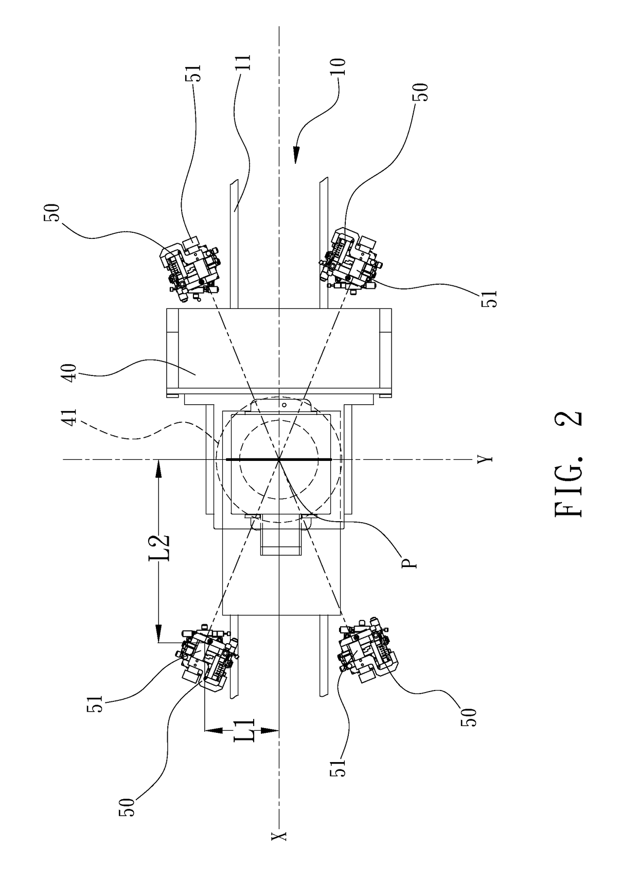
[0020]Referring to FIGS. 1 through 3, there is a machine for detecting tiny particles on a transparent plate 80 such as a mask in the semiconductor industry. The machine includes a frame 10, a carrier module 20, an optical module 40 and at least two illumination modules 50. The frame 10 supports the carrier module 20, the optical module 40 and the illumination modules 50. The carrier module 20 carries a transparent plate 80 in need of inspection. The optical module 40 inspects the transparent plate 80. The optical module 40 is rectilinearly movable relative to the carrier module 20. The illumination modules 50 are located around the optical module 40, and each of them casts a spot of light on the transparent plate 80.

[0021]The frame 10 does not only support the carrier module 20 and the optical module 40 but also supports controlling elements, pneumatic elements and other related elements. The frame 10 includes a guiding unit 15 that includes at least one rectilinear track (not numb...


PUM


Abstract

A machine for inspecting a face of a transparent plate includes a frame, a carrier module, an optical module and at least two illumination modules. The frame includes an X-axis. The carrier module is adapted for carrying a transparent plate in need of inspection on the frame along the X-axis. The optical module is located on the frame and movable relative to the carrier module and includes at least one detector adapted for rectilinear scanning along a Y-axis perpendicularly intersecting the X-axis of the carrier module at a crossing point. The illumination modules are located on two opposite sides of the X-axis of the frame. Each of the illumination modules includes a laser emitter. The laser emitters are located at a same distance from the crossing point and adapted for emitting rays on the transparent plate at a same angle of 0.5° to 6°.

Description

BACKGROUND OF INVENTION[0001]1. Field of Invention[0002]The present invention relates to inspection of a transparent plate and, more particularly, to a machine for detecting tiny particles on a face of a transparent element without risks of being affected by a pattern on an opposite face of the transparent plate.[0003]2. Related Prior Art[0004]A conventional mask-inspecting apparatus includes an optical module such as an image sensor, a CCD and a CMOS element to scan a face of a mask to detect contaminant or sediment. For example, when the optical module casts light on an upper face of the mask, which is made of a glass plate that is transparent, a pattern on a lower face of the mask jeopardizes the precision, effect and efficiency of inspection of tiny particles on the upper face of the mask.[0005]Another optical module is based on scanning a mask with a ray such as a laser or an electron beam. The ray casts a small spot of light on the mask. However, such an optical module is expe...

Claims


Application Information

Patent Timeline
IPC IPC(8): G01N21/94G01N21/958G01N21/95
CPCG01N21/94G01N21/9501G01N2201/105G01N2201/12G01N2201/0612G01N21/958
Inventor CHEN, MING-SHENG
Owner CHEN MING SHENG
Why Eureka
Try Eureka