An energy feedback system and method for an electric drive automatic transmission

A technology of automatic transmission and energy feedback, applied in electric braking system, electric vehicle, electric energy management, etc., can solve the problems of high cost and complex structure, and achieve the effect of reducing cost and simplifying system structure.

Active Publication Date: 2017-12-05
武汉理工通宇新源动力有限公司
View PDF5 Cites 3 Cited by
  • Summary
  • Abstract
  • Description
  • Claims
  • Application Information

AI Technical Summary

Problems solved by technology

However, for non-electrically driven vehicles, the structure of this electric-driven automatic transmission system is relatively complicated and the cost is relatively high.

Method used


Image

  • An energy feedback system and method for an electric drive automatic transmission
  • An energy feedback system and method for an electric drive automatic transmission

Examples


Embodiment Construction

[0039] The present invention will be further described below in conjunction with specific examples and accompanying drawings.

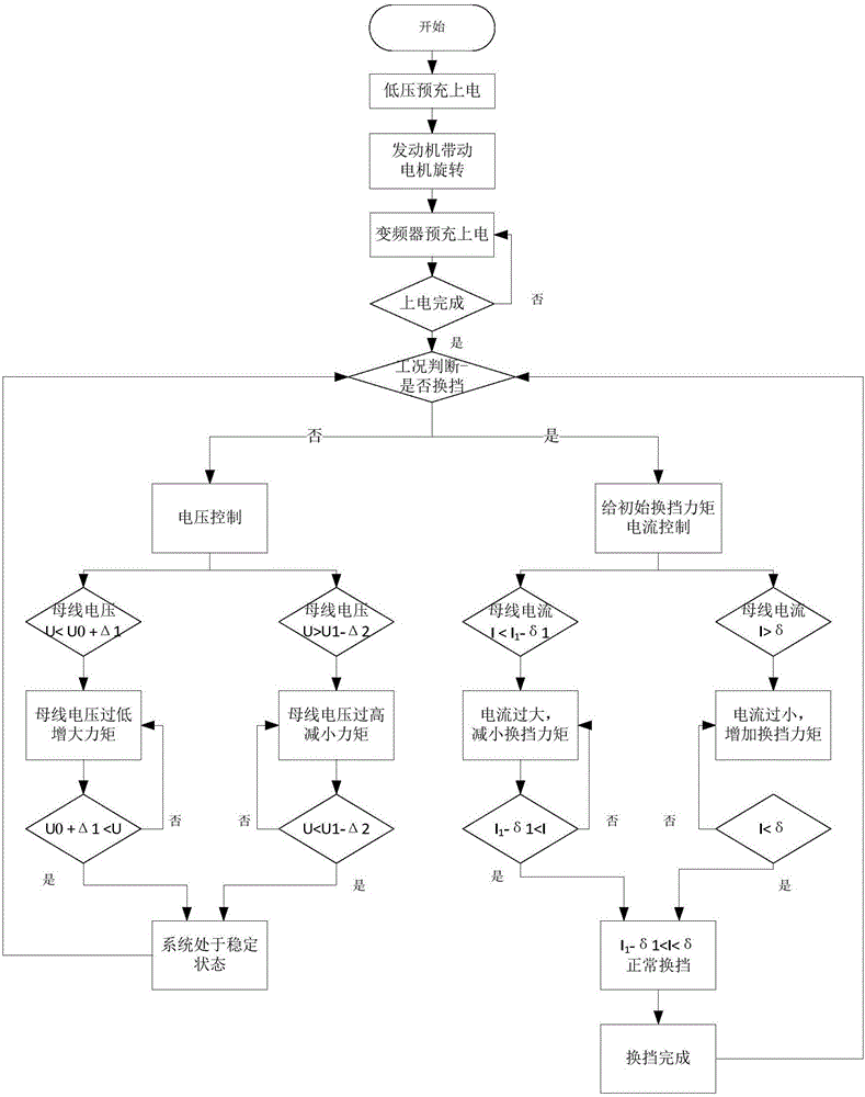
[0040] An energy feedback method for driving an automatic transmission, such as figure 2 As shown, it includes the following steps:

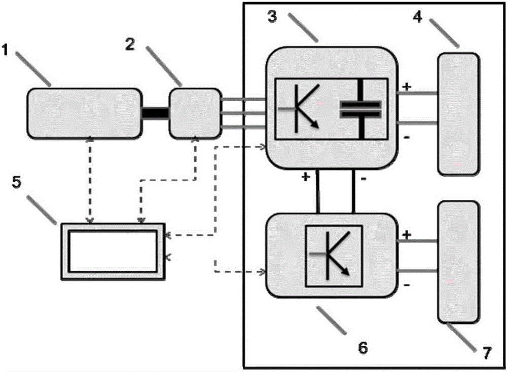
[0041] S1. Low-voltage pre-charging: Use the vehicle-mounted low-voltage DC power supply to perform low-voltage pre-charging on the capacitor of the inverter.

[0042] S2. Power on: The permanent magnet motor is driven and rotated by the engine, and the IGBT of the permanent magnet motor controller rectifies the three-phase alternating current at the permanent magnet motor end into direct current to charge the capacitor of the frequency converter, and the charging is controlled by controlling the rotational speed of the engine The process until the threshold voltage value of the permanent magnet motor controller is reached.

[0043] S3. Normal operation: After the inverter is powered on, it controls the permanent mag...


PUM


Abstract

The invention provides an electric drive automatic transmission energy feedback method. A capacitor of a frequency converter is charged by low voltages through a vehicle-mounted low-voltage DC power supply in advance. Three-phase alternating currents of a permanent magnet motor end are rectified into direct currents through an IGBT of a permanent magnet controller so that the capacitor of the frequency converter can be charged. The charging process is controlled by controlling the rotating speed of the engine till the threshold voltage value of the working permanent magnet motor controller is reached. When the gear is not shifted, the voltage is stabilized, and the system is in a dynamic balanced state; when the gear is shifted, the permanent magnet motor executes speed adjustment, and the currents are controlled within the allowable range in the speed regulation process; when the permanent magnet motor executes speed-reduction power generation, a brake control unit is controlled to switch off a brake resistance circuit and sends fed-back power to a brake resistor to be consumed. By means of the method, use working conditions of an electric drive automatic transmission are met; meanwhile, a power supply part in the electric drive automatic transmission is replaced, an independent matched power supply system is not needed for the gear changing permanent magnet motor, and the aims of simplifying the system structure and reducing cost are achieved.

Description

technical field [0001] The invention relates to a mechanical power transmission speed change device, in particular to an energy feedback system and method for an electric-driven automatic transmission. Background technique [0002] In a general electric-driven automatic transmission, the permanent magnet motor is driven to adjust the speed and shift gears, and the energy required to drive the permanent magnet motor comes from energy storage devices such as batteries and super capacitors. When the permanent magnet motor is driven to increase speed, the electric energy stored in the power supply is converted into mechanical energy to drive the permanent magnet motor to increase speed; when the permanent magnet motor is driven to decelerate, the mechanical energy to drive the permanent magnet motor is converted into electrical energy and stored in the power supply. Therefore, it is necessary to be equipped with a special power supply and power management system. However, for n...

Claims


Application Information

Patent Timeline
Patent Type & Authority Patents(China)
IPC IPC(8): B60L7/06
CPCB60L7/06Y02T10/72
Inventor 曹正策张子起汤治恒俞鹏飞
Owner 武汉理工通宇新源动力有限公司
Why Eureka
Try Eureka