
High-performance single-clack dual-seal pneumatic adjusting valve for nuclear power

A pneumatic regulating valve, a high-performance technology, applied in the direction of shaft sealing, valve lift, valve details, etc., can solve the problems of unsuitable nuclear power unit opening or closing control, large damage, large opening and closing torque of the regulating valve, etc., to achieve operating torque Small size, long service life, good sealing performance

Inactive Publication Date: 2020-04-17
南通国电阀门科技有限公司
View PDF3 Cites 1 Cited by
  • Summary
  • Abstract
  • Description
  • Claims
  • Application Information

AI Technical Summary

Problems solved by technology

[0002] The traditional opening and closing parts, the medium will cause great damage to the valve core shaft and valve disc at the moment of valve opening and closing, and the opening and closing torque of the regulating valve is large, which is not suitable for the opening or closing control of nuclear power units

Method used


Image

  • High-performance single-clack dual-seal pneumatic adjusting valve for nuclear power
  • High-performance single-clack dual-seal pneumatic adjusting valve for nuclear power

Examples


Embodiment Construction

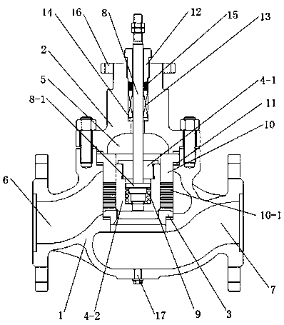
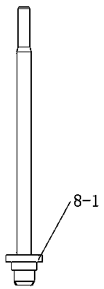
[0015] Such as Figure 1-2 As shown, a high-performance single-plate double-sealed pneumatic regulating valve for nuclear power includes a valve body 1, a valve cover 2, a valve seat 3, and a valve clack assembly 4. The valve cover 2 is installed on the valve body 1 to form a valve cavity 5. Both ends of the valve body 1 are respectively provided with an inlet 6 and an outlet 7. The inlet 6 communicates with the upper part of the valve cavity 5, the outlet 7 communicates with the bottom of the valve cavity 5, and the valve seat 3 is horizontally arranged in the valve cavity 5 and is detachable from the valve body 1. Connected, located at the junction of the outlet 7 and the valve cavity 5. The valve disc assembly 4 is arranged on the valve seat 3, and the valve core shaft 8 drives it to move up and down in the valve cavity 5 to open or close the valve; the disc assembly 4 includes The disc 4-1 is opposite to the valve seat 3, the disc 4-1 is opposite to the valve seat 3, and th...


PUM


Abstract

The invention relates to a high-performance single-clack dual-seal pneumatic adjusting valve for nuclear power. The high-performance single-clack dual-seal pneumatic adjusting valve comprises a valvebody, a valve cover, a valve seat and a valve clack assembly. The valve cover is mounted on the valve body, and a valve cavity is formed. An inlet and an outlet are arranged at the two ends of the valve body correspondingly. The valve seat and the valve clack assembly are mounted in the valve cavity in a cooperation manner, and the valve clack assembly is driven by a valve element shaft to move upand down in the valve cavity, so that the valve is opened or closed. The valve clack assembly comprises a first valve clack and a second valve clack, the first valve clack and the valve seat are opposite and are in seal fit to form outer seal, a round groove is formed in the top of the second valve clack, a round hole is formed in the bottom of the round groove, and the first valve clack covers the second valve clack. The valve element shaft sequentially penetrates through the valve cover, the valve cavity and the first valve clack in the vertical direction to stretch into the round groove, aring protrusion is arranged on the valve element shaft, the lower end of the valve element shaft is opposite to the round hole, and the valve element shaft and the round hole are in seal fit to forminner seal. The valve element shaft is further sleeved with a spring, and the two ends of the spring are fixed to the ring protrusion and the second valve clack correspondingly. The sealing performance is good, the operation torque is small, the service life is long, the cost is reduced, benefits are increased, and the use conditions of a nuclear unit are met.

Description

Technical field [0001] The invention relates to a valve, in particular to a high-performance single-valve double-sealed pneumatic regulating valve for nuclear power. Background technique [0002] Traditional opening and closing parts have great damage to the valve core shaft and valve clack at the moment of opening and closing of the valve, and the opening and closing torque of the regulating valve is large, which is not suitable for the opening or closing control of nuclear power plants. Summary of the invention [0003] In order to solve the above-mentioned problems, the present invention proposes a high-performance single-plate double-sealed pneumatic regulating valve for nuclear power that is suitable for opening or closing control of nuclear power plants and has good sealing performance, small operating torque and long service life. [0004] The technical scheme of the present invention: [0005] A high-performance single-plate double-sealed pneumatic regulating valve for nuclea...

Claims


Application Information

Patent Timeline
IPC IPC(8): F16K1/36F16K1/32F16K27/02F16K27/12F16K41/02F16K31/12
CPCF16K1/32F16K1/36F16K27/02F16K27/12F16K31/12F16K41/02
Inventor 尤辉宏韩健莉阮淋波周国林倪剑张益龙
Owner 南通国电阀门科技有限公司
Learn More