
A continuous feed tearing machine

A technology of tearing machine and feeding port, which is applied in the direction of fiber opening and cleaning machine, agitation and cleaning, etc. It can solve the problem of rolling off a large group, sometimes with little rolling, the tearing machine cannot be completely torn apart, and there is no transportation Roller device and other problems, to achieve the effect of small equipment burden, simple structure and high production efficiency

Active Publication Date: 2018-05-01
徐州天骋智能科技有限公司
View PDF5 Cites 0 Cited by
  • Summary
  • Abstract
  • Description
  • Claims
  • Application Information

AI Technical Summary

Problems solved by technology

[0002] In textile and printing and dyeing enterprises, at the beginning of processing, most fiber raw materials such as fiber, cotton, and cloth need to be unpacked and unpacked to remove impurities and obtain fine raw materials. However, some of the existing wool tearing machines are not equipped for easy loading For the cotton conveying roller device, the feeding is intermittent, which will lead to a decrease in work efficiency; even if there is a conveying roller device, because the raw material is in the form of a block, sometimes a large ball will roll off when feeding, sometimes there will be little rolling, and a large ball will roll off Sometimes the wool tearing machine cannot be completely torn apart, and the final raw materials are still formed into small pieces, not fluffy, which cannot meet the processing requirements of the next process.

Method used


Image

  • A continuous feed tearing machine

Examples


Embodiment Construction

[0018] The present invention will be further explained below in conjunction with the accompanying drawings and specific embodiments. It should be understood that the following specific embodiments are only used to illustrate the present invention and are not intended to limit the scope of the present invention. It should be noted that the words "front", "rear", "left", "right", "upper" and "lower" used in the following description refer to the directions in the drawings, and the words "inner" and "outer ” refer to directions towards or away from the geometric center of a particular part, respectively.

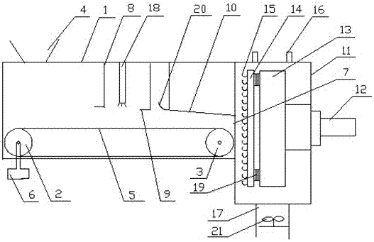
[0019] As shown in the figure, a continuous feed tearing machine according to the present invention includes a conveying roller device and a cabinet 11, and the conveying roller device includes a bracket 1, a driving roller 2 and a driven roller 3, and on the bracket 1 There is a feeding port 4, and the driving roller 2 and the driven roller 3 are arranged below the feeding por...


PUM


Abstract

The invention discloses a wool tearing machine capable of achieving continuous feeding. The wool tearing machine comprises a conveyer roll device and a machine case; the conveyer roll device comprises a support, a drive roll and a driven roll, the support is provided with a feed port, the outer circle of the drive roll and the outer circle of the driven roll are wrapped with a belt, the drive roll is connected with a first motor, a material outlet is formed in the position above the right side of the belt, at least one row of limit pins are arranged above the belt, the lowermost end of each limit pin is provided with a right angle hook, and an inclined limit plate is arranged on the right sides of the limit pins; the machine case is arranged on the right side of the conveyer roll device, the right side of the machine case is provided with a second motor which is connected with a vertical rotary disc arranged in the machine case, the left side of the rotary disc is provided with an adjustable flat plate, the left side of the flat plate is provided with hooks, downward air nozzles are arranged on the machine case, and a discharge pipe is arranged under the machine case. According to the wool tearing machine capable of achieving continuous feeding, tearing is firstly performed for one time in the feeding process to compress the material feeding height, feeding is continuous and ordered, the wool tearing effect is good, and a produced material is fluffy, fine and soft; the structure is simple, use is convenient, the safety is high, the equipment burden is small, and the production efficiency is high.

Description

technical field [0001] The invention belongs to the technical field of textile machinery, and in particular relates to a continuous feeding wool tearing machine. Background technique [0002] In textile and printing and dyeing enterprises, at the beginning of processing, most fiber raw materials such as fiber, cotton, and cloth need to be unpacked and unpacked to remove impurities and obtain fine raw materials. However, some existing wool tearing machines are not equipped for easy loading. For the cotton conveying roller device, the feeding is intermittent, which will lead to a decrease in work efficiency; even if there is a conveying roller device, because the raw material is in the form of a block, sometimes a large ball will roll off when feeding, and sometimes there will be little rolling, and a large ball will roll off Sometimes the wool tearing machine cannot completely tear it apart, and the final raw materials still form small pieces, which are not fluffy and cannot ...

Claims


Application Information

Patent Timeline
Patent Type & Authority Patents(China)
IPC IPC(8): D01G9/02D01G9/16
CPCD01G9/02D01G9/16
Inventor 孙在强
Owner 徐州天骋智能科技有限公司
Learn More