
A high-efficiency multi-compartment wool tearing machine

A tearing machine, high-efficiency technology, applied in the field of high-efficiency multi-compartment wool tearing machine, can solve the problems of not being fluffy, low production efficiency, etc., and achieve the effect of improving the degree of porosity, high production efficiency and long service life

Active Publication Date: 2018-02-13
孙习习
View PDF5 Cites 0 Cited by
  • Summary
  • Abstract
  • Description
  • Claims
  • Application Information

AI Technical Summary

Problems solved by technology

[0002] In textile, printing and dyeing enterprises, at the beginning of processing, most fiber raw materials such as fiber, cotton, and cloth need to be unpacked and wool-teared to remove impurities and obtain fine raw materials. The wool-tearing work of some fiber raw materials is carried out simultaneously with other processes. The wool tearing machine is a commonly used loosening device in the prior art. The wool tearing machine in the prior art generally uses a curtain and a roller planted with corner nails to loosen large pieces of fiber, and then rotates at a high speed in a closed casing. The blades hit the loose fiber pieces, and the final raw materials still form small pieces, which are not fluffy and cannot meet the processing requirements of the next process. It is often necessary to repeatedly tear the wool to meet the fiber looseness requirements. low production efficiency

Method used


Image

  • A high-efficiency multi-compartment wool tearing machine
  • A high-efficiency multi-compartment wool tearing machine

Examples


Embodiment Construction

[0019] The present invention will be further explained below in conjunction with the accompanying drawings and specific embodiments. It should be understood that the following specific embodiments are only used to illustrate the present invention and are not intended to limit the scope of the present invention. It should be noted that the words "front", "rear", "left", "right", "upper" and "lower" used in the following description refer to the directions in the drawings, and the words "inner" and "outer ” refer to directions towards or away from the geometric center of a particular part, respectively.

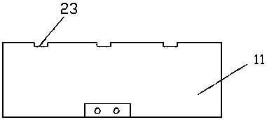
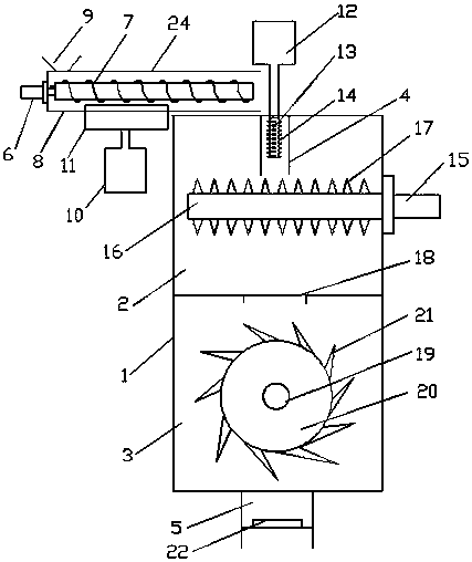
[0020] As shown in the figure, a high-efficiency multi-compartment wool tearing machine according to the present invention includes a box body 1 and an auger conveyor. Feed pipe 4, discharge pipe 5 is provided below the lower machine bin 3, and the auger conveyor includes a motor one 6 and a screw blade 7, and a supporting plate 8 is provided below the screw blade 7, and a moto...


PUM


Abstract

The invention discloses an efficient multi-bin fibrous material tearing machine. The machine comprises a box body and an auger conveyer, wherein the interior of the box body is divided into an upper bin and a lower bin, a feeding pipe is arranged on one side of the upper portion of the upper bin, a discharging pipe is arranged on the lower portion of the lower bin, a first cylinder is arranged on the lower portion of the auger conveyer and connected with a baffle, and the upper edge of the baffle is 3-10 mm away from a screw blade; a second cylinder is arranged on the upper portion of the feeding pipe and connected with a fibrous material tearing column, and barbs are arranged on the surface of the fibrous material tearing column; a second motor is arranged on the outer side of the upper bin and connected with a horizontal stirring shaft, and spines are arranged on the horizontal stirring shaft in a stagger mode; fibrous material falling holes are formed in the lower plane of the upper bin, a third motor is arranged at one end of the lower bin and connected with a longitudinal stirring shaft, brads are arranged on the longitudinal stirring shaft in a stagger mode, and a suction fan is arranged in the discharging pipe. According to the machine, multi-bin processing is conducted, materials are torn multiple times in different directions, a product is fluffy, fine and soft, equipment burden is small, service life is long, and production efficiency is high.

Description

technical field [0001] The invention belongs to the technical field of textile machinery, and in particular relates to a high-efficiency multi-compartment wool tearing machine. Background technique [0002] In textile, printing and dyeing enterprises, at the beginning of processing, most fiber raw materials such as fiber, cotton, and cloth need to be unpacked and wool-teared to remove impurities and obtain fine raw materials. The wool-tearing work of some fiber raw materials is carried out simultaneously with other processes. The wool tearing machine is a commonly used loosening device in the prior art. The wool tearing machine in the prior art generally uses a curtain and a roller planted with corner nails to loosen large pieces of fiber, and then rotates at a high speed in a closed casing. The blades hit the loose fiber pieces, and the final raw materials are still formed into small pieces, which are not fluffy and cannot meet the processing requirements of the next proces...

Claims


Application Information

Patent Timeline
Patent Type & Authority Patents(China)
IPC IPC(8): D01G9/06D01G11/00
CPCY02W30/66
Inventor 孙习习
Owner 孙习习
Learn More