Paper pulp bleaching equipment use method
A pulp and equipment technology, applied in the field of pulp bleaching equipment, can solve the problems of reducing the bleaching effect of pulp, failing to reach the optimal concentration of bleaching agent, and low work efficiency, and achieve the effect of improving the bleaching effect
- Summary
- Abstract
- Description
- Claims
- Application Information
AI Technical Summary
Problems solved by technology
Method used
Image

Examples
Embodiment 1
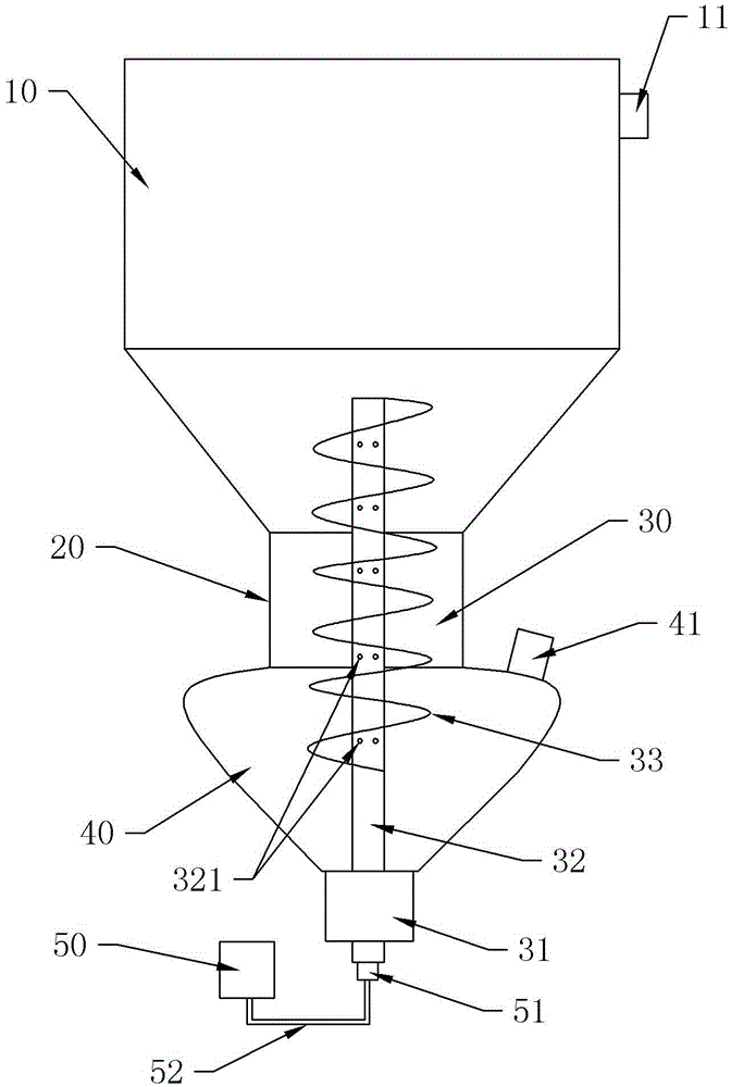
[0021] Embodiment 1 is basically as attached figure 1 Shown: a bleaching equipment for pulp, including a bleaching tower 10, the upper part of the bleaching tower 10 is provided with a discharge port 11, and the bottom of the bleaching tower 10 is provided with a feed port and a feed channel 20 communicating with the feed port. The embodiment also includes a storage hopper 40, a bleach box 50, and a feeding mechanism 30. The storage hopper 40 is located below the bleaching tower 10, and the feed passage 20 communicates with the upper end of the storage hopper 40. A feeding port 41 is provided on the storage hopper 40, and the storage hopper The lower part of 40 is funnel-shaped. The spiral blade 33 can send out the pulp in the lower part of the storage hopper 40 to avoid the accumulation of pulp in the lower part of the storage hopper 40 . The feeding mechanism 30 includes a rotating shaft 32 with a hollow cavity, a helical blade 33 and a power source 31 for driving the rotat...
Embodiment 2
[0028] The difference from Embodiment 1 is that: the helical blade 33 is provided with a distributing chamber communicating with the hollow cavity, and the helical blade 33 is provided with a distributing hole communicating with the distributing chamber. In this scheme, also offer dispensing cavity and distribution hole on the helical blade 33, the bleaching agent not only sprays through the spray hole 321 on the rotating shaft 32, but also can be sprayed from the surface of the helical blade 33, because the helical blade 33 is always in the In the state of pushing the pulp, the contact surface between the helical blade 33 and the pulp is large, so the bleaching agent can be dispersed in the pulp to a greater extent.
[0029] The specific method of use of the present embodiment is different from the method of embodiment 1 as follows:
[0030] Step 3: (3) Simultaneously with step 2, the bleach in the bleach tank 50 is pumped into the hollow cavity of the rotating shaft 32 and t...
Embodiment 3
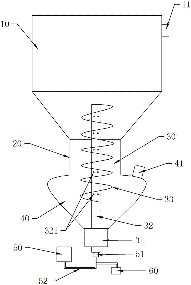
[0032] Such as figure 2 As shown, the difference from Embodiment 1 is that: it also includes a blower device 60, the blower device 60 in this embodiment is a blower, and the air outlet of the blower communicates with the hollow cavity through an air pipe. When blowing air into the hollow cavity, the bleach in the hollow cavity can be sprayed out from the spray hole 321 in a spray state, which can make the bleach more dispersed.
[0033] The specific method of use of the present embodiment is different from the method of embodiment 1 as follows:
[0034] At the same time of step 2, the blower is also started to blow air into the hollow cavity of the rotating shaft 32;
PUM
 Abstract
Description
Claims
Application Information
 - R&D Engineer
- R&D Manager
- IP Professional
- Industry Leading Data Capabilities
- Powerful AI technology
- Patent DNA Extraction
Browse by: Latest US Patents, China's latest patents, Technical Efficacy Thesaurus, Application Domain, Technology Topic.
© 2024 PatSnap. All rights reserved.Legal|Privacy policy|Modern Slavery Act Transparency Statement|Sitemap