Locking pin

A technology of locking pins and pin holes, applied in the direction of building fastening devices, buildings, building structures, etc., can solve the problems of low safety and inconvenient operation, and achieve simple structure, convenient installation, and easy operation. convenient effect

Inactive Publication Date: 2016-03-09
赵沅飞
View PDF6 Cites 0 Cited by
  • Summary
  • Abstract
  • Description
  • Claims
  • Application Information

AI Technical Summary

Problems solved by technology

[0002] At present, the existing locking pins on the market are generally push-pull, and the locking pins are pushed or pushed into a fixed hole. For example, the publication number applied for in China is 103899165A. The patent of tight pin, it is made up of pin plate (1), pin bolt (2), latch hoop (3), pin nose (4), nostril (5), baffle plate (6) and installation hole (7), user The function of locking the doors and windows can be realized only by pushing the pi

Method used


Image

  • Locking pin
  • Locking pin
  • Locking pin

Examples


Embodiment Construction

[0026] Below in conjunction with accompanying drawing and embodiment the present invention is described in further detail:

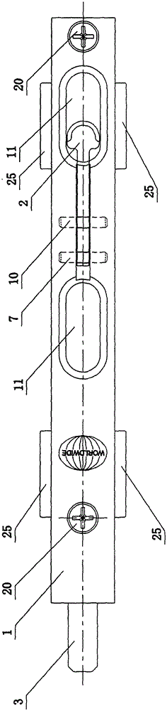
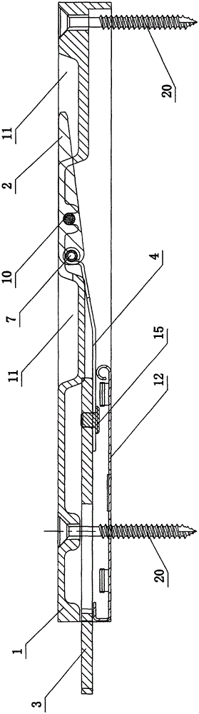
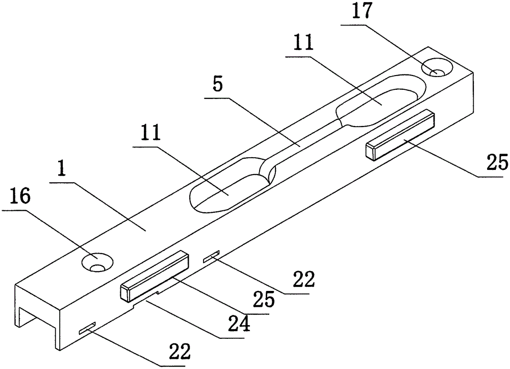
[0027] As an embodiment of the locking pin of the present invention, such as figure 1 , figure 2 , image 3 , Figure 4 , Figure 5 , Figure 6 , Figure 7 and Figure 8 As shown, it includes a housing 1, a handle 2, a connecting rod 3 and a spring leaf 4. The housing 1 is provided with a slot 5 for the handle, and the inner end of the handle 2 is inserted into the slot 5 for the handle. Inside, the inner end of the dial handle 2 is provided with a first pin hole 6, which is rotationally connected with one end of the spring leaf 4 through the first cylindrical pin 7, and the other end of the spring leaf 4 is connected with the connecting rod 3 One end is connected, the connecting rod 3 and the spring leaf 4 are located inside the housing 1, the other end of the connecting rod 3 extends out of the housing 1, and the middle part of the dial handle ...


PUM


Abstract

The invention relates to the technical field of house decoration, in particular to a locking pin. The locking pin comprises a shell, a shifting handle, a connection rod and a leaf spring. A shifting handle groove is formed in the shell. The inner end of the shifting handle is inserted into the shifting handle groove. A first pin hole is formed in the inner end of the shifting handle. The inner end of the shifting handle is rotationally connected with one end of the leaf spring through a first cylindrical pin. The other end of the leaf spring is connected with one end of the connection rod. The connection rod and the leaf spring are located inside the shell. The other end of the connection rod extends out of the shell. A second pin hole is formed in the middle of the shifting handle. A pin groove is formed in the inner surface of the shell. The shifting handle is rotationally connected with the shell through a second cylindrical pin. Two grooves are formed in the positions, on the two sides of the shifting handle groove, of the outer surface of the shell respectively. The outer end of the shifting handle is located inside the grooves. A cover plate is arranged on the back face of the shell and located on the outer sides of the leaf spring and the connection rod. The locking pin is simple in structure, convenient to install and operate, safe and reliable.

Description

technical field [0001] The invention relates to the technical field of house decoration, in particular to a locking pin. Background technique [0002] At present, the existing locking pins on the market are generally push-pull, and the locking pin is pushed or pushed into a fixed hole. For example, the publication number of the application in China is 103899165A. The patent of tight pin, it is made up of pin plate (1), pin bolt (2), latch hoop (3), pin nose (4), nostril (5), baffle plate (6) and installation hole (7), user The function of locking the doors and windows can be realized only by pushing the pin (2) into the nostril (5), but in this structure, the pin (2) must slide in the latch hoop (3), and the pin There must be a gap between the bolt (2) and the bolt hoop (3), and then there is misalignment when the bolt (2) is inserted into the nostril (5), which is not very convenient for the user to operate, so it has certain limitations In addition, this structure is exp...

Claims


Application Information

Patent Timeline
IPC IPC(8): E05C1/12
CPCE05C1/12
Inventor 赵沅飞
Owner 赵沅飞
Why Eureka
Try Eureka