semi-active hydraulic mount

A hydraulic mount, semi-active technology, applied in the direction of shock absorbers, springs, springs/shock absorbers, etc., can solve the problems of inability to meet shock absorption requirements, complex structure, high cost, and achieve simple structure, good reliability, low cost effect

Active Publication Date: 2018-01-16
ZHEJIANG SHITAI IND CO LTD
View PDF6 Cites 1 Cited by
  • Summary
  • Abstract
  • Description
  • Claims
  • Application Information

AI Technical Summary

Problems solved by technology

However, the existing hydraulic mounts still have the following disadvantages: the existing hydraulic mounts usually only have a good shock absorption effect in a certain frequency range, and cannot meet the shock absorption requirements in the entire working range of the car
The newly proposed active mount technology makes up for the lack of high-frequency performance of traditional hydraulic mounts through active actuators for shock absorption in the high-frequency range, but its structure is complex and the cost is high

Method used


Image

  • semi-active hydraulic mount
  • semi-active hydraulic mount

Examples


Embodiment 1

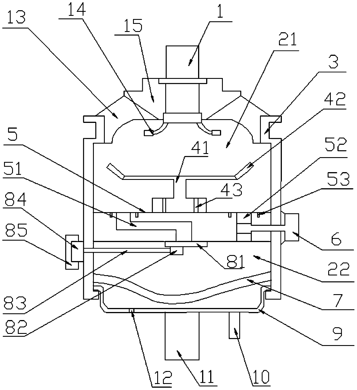
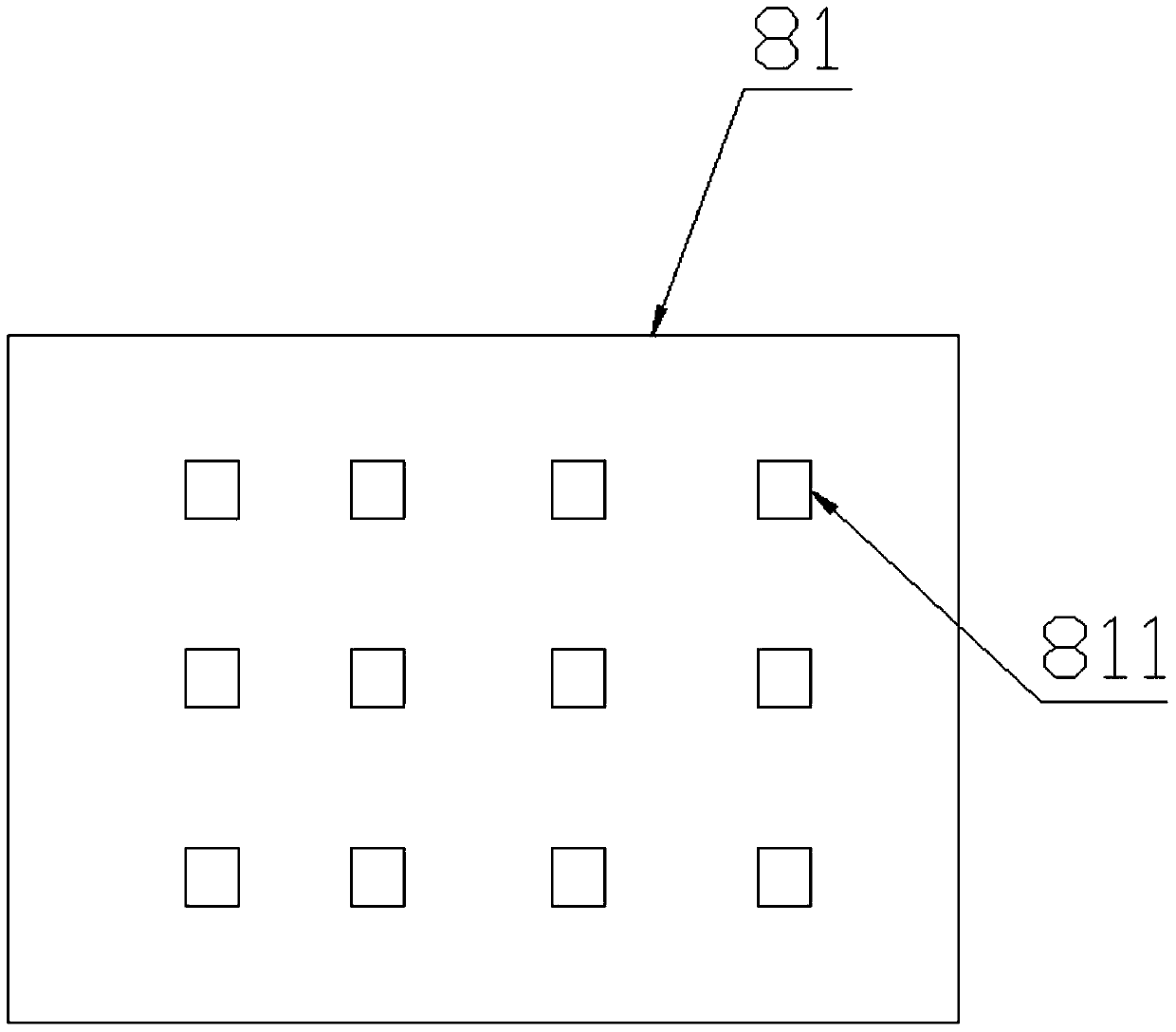
[0019] Semi-active hydraulic mounts, such as Figure 1-2 Shown, comprise rubber main spring 13, housing 3 and base film 7, rubber main spring 13, housing 3 and base film 7 encircle a cavity, be provided with vibration isolation mechanism 5 in the cavity, vibration isolation mechanism 5 will cavity Divided into an upper liquid chamber 21 and a lower liquid chamber 22, a first channel 51 and a second channel 52 are provided in the vibration isolation mechanism 5, and a cover plate 81 is arranged below the first channel 51 on the vibration isolation mechanism 5, and a cover plate 81 is provided on the cover plate 81. There are ten square holes 811, the housing 3 is provided with a motor 84, the motor 84 is provided with a lifting shaft 83, and the lifting shaft 83 is provided with a current limiting block 82, and the current limiting block 82 controls the closing of the square holes 811. The current limiting block 82 controls the flow rate of the liquid in the first channel 51 by...


PUM


Abstract

The invention relates to automobile parts and discloses a semi-active hydraulic suspension. The semi-active hydraulic suspension comprises a rubber main spring (13), a shell (3) and a bottom film (7). A cavity is defined by the rubber main spring (13), the shell (3) and the bottom film (7) in an enclosed mode. A vibration isolation mechanism (5) is arranged in the cavity and divides the cavity into an upper liquid chamber (21) and a lower liquid chamber (22). A first channel (51) and a second channel (52) are formed in the vibration isolation mechanism (5). A cover plate (81) is arranged on the vibration isolation mechanism (5) and located below the first channel (51). The cover plate (81) is provided with at least one square hole (811). A motor (84) is arranged on the shell (3) and provided with a lifting shaft (83). The lifting shaft (83) is provided with a flow limiting block (82) which controls opening and closing of the square holes (811). The dynamic characteristics of the hydraulic suspension are controlled through the motor, so that the semi-active hydraulic suspension meets the requirements for vibration reduction under different working conditions.

Description

technical field [0001] The invention relates to auto parts, in particular to a semi-active hydraulic mount. Background technique [0002] Automotive engine hydraulic mount refers to the elastic connection system between the engine powertrain and the vehicle frame. The design of the system's vibration damping performance is directly related to the transmission of engine vibration to the vehicle body, which affects the NVH performance of the vehicle. The hydraulic mount is an important part of the car, mainly used to reduce the vibration transmitted from the engine to the body, while controlling the displacement of the engine, resisting the torque of the engine, and reducing the impact transmitted from the tire to the powertrain on potholed roads. Therefore, it is required that the hydraulic mount not only has good vibration isolation ability, but also has a good ability to block shock. Existing hydraulic mounts mainly include simple orifice type, inertial channel type, and i...

Claims


Application Information

Patent Timeline
Patent Type & Authority Patents(China)
IPC IPC(8): F16F13/00F16F9/32
CPCF16F9/3207F16F13/00
Inventor 陈建会陈中敢
Owner ZHEJIANG SHITAI IND CO LTD
Why Eureka
Try Eureka