Cylindrical eddy current damping device, damping regulation method and bridge vibration attenuation structure

A technology of eddy current damping and damping devices, which is applied in the direction of bridges, bridge parts, bridge construction, etc., can solve the problems that the damping proportional coefficient of the damper is not easy to change and adjust, affects the normal working performance of the shock absorber, and has little damping effect, etc. , to avoid the gradual accumulation of fatigue and damage, to clarify the principle of vibration reduction, and to increase the speed of energy dissipation

Active Publication Date: 2018-08-21
CHINA RAILWAY BRIDGE SCI RES INST LTD +1
View PDF14 Cites 1 Cited by
  • Summary
  • Abstract
  • Description
  • Claims
  • Application Information

AI Technical Summary

Problems solved by technology

Generally, oil dampers are related to the problem of oil leakage; liquid grids are used to provide damping. When the required damping force is large, the damping effect is very small. In addition, there are certain problems in the stability of damping parameters, which affect the shock absorber. normal working performance; some researchers also use fluid-solid coupling vibration to completely separate mass parameters, stiffness parameters and damping parameters, so that although tuning is convenient, the damping proportional coefficient of this damper is not easy to change and adjust

Method used


Image

  • Cylindrical eddy current damping device, damping regulation method and bridge vibration attenuation structure
  • Cylindrical eddy current damping device, damping regulation method and bridge vibration attenuation structure
  • Cylindrical eddy current damping device, damping regulation method and bridge vibration attenuation structure

Examples


Embodiment Construction

[0025] The present invention will be further described in detail below in conjunction with the accompanying drawings and specific embodiments.

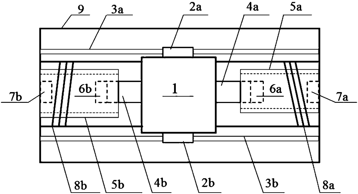
[0026] see figure 1 As shown, the embodiment of the present invention provides a cylindrical eddy current damping device, the damping device includes a support frame 9, a mass 1, a strong induction magnet, a linear guide rail and a copper tube; the two ends of the linear guide rail are fixed to the support frame 9 connection, the mass block 1 is slidably set along the linear guide rail, the induction strong magnet includes a first induction strong magnet 6a and a second induction strong magnet 6b, the copper tube includes a first copper tube 5a and a second copper tube 5b, and the first induction strong magnet 6a and the second induction strong magnet 6b are respectively arranged on both sides of the mass block 1, and the first copper tube 5a and the second copper tube 5b are respectively arranged on both sides of the supporting frame...


PUM


Abstract

The invention discloses a cylindrical eddy current damping device, a damping regulation method and a bridge vibration attenuation structure, and relates to the technical field of vibration attenuationdevices. The damping device comprises a supporting frame, a mass block, an induction strong magnet, a straight line guide rail and a copper pipe, wherein the induction strong magnet comprises a firstinduction strong magnet and a second induction strong magnet; the copper pipe comprises a first copper pipe and a second copper pipe; the first induction strong magnet and the second induction strongmagnet are respectively arranged at two sides of the mass block; the first copper pipe and the second copper pipe are respectively arranged at two sides of the supporting frame; when the mass block vibrates, the first induction strong magnet and the second induction strong magnet respectively carry out reciprocating motion in the first copper pipe and the second copper pipe. According to the damping regulation method, the internal radius and the external radius of the copper pipe and the size of the induction strong magnet are regulated to realize different damping coefficients. The bridge vibration attenuation structure comprises the damping device. Through a Ferrari electromagnetic induction principle, the energy of structure vibration is adsorbed, and a damping proportionality coefficient can be conveniently regulated.

Description

technical field [0001] The invention relates to the technical field of damping devices, in particular to a cylindrical eddy current damping device, a damping adjustment method and a bridge damping structure. Background technique [0002] With the continuous development of materials and mechanical equipment technology, the span of bridges and other engineering structures is getting larger and larger, and the key support structures are getting higher and higher. Under the action of external dynamic loads such as earthquakes or strong winds, the structure will produce a relatively strong dynamic response. The rigidity of the structure is seriously reduced, and the fatigue and damage of the structure gradually accumulate, which eventually leads to the worsening of the safety and health of the structure. Structural vibration control can effectively reduce the response and damage accumulation of structures under the dynamic effects of wind, earthquake, and vehicles, and effectivel...

Claims


Application Information

Patent Timeline
Patent Type & Authority Applications(China)
IPC IPC(8): F16F15/03E01D19/00
CPCF16F15/035E01D19/00
Inventor 王波王翔苏从辉汪正兴荆国强马长飞柴小鹏伊建军刘鹏飞王梓宇吴肖波阮小丽
Owner CHINA RAILWAY BRIDGE SCI RES INST LTD
Why Eureka
Try Eureka