Vibration reduction method for aeolian vibration of circular tube components of power transmission tower
A technology for transmission towers and circular pipes, which is applied to building components, towers, and anti-vibration, can solve problems such as high cost, unsuitable vibration damping, and complex structure of vibration shock absorbers. The effect of vibration reduction effect
- Summary
- Abstract
- Description
- Claims
- Application Information
AI Technical Summary
Problems solved by technology
Method used
Image
Examples
Embodiment 1
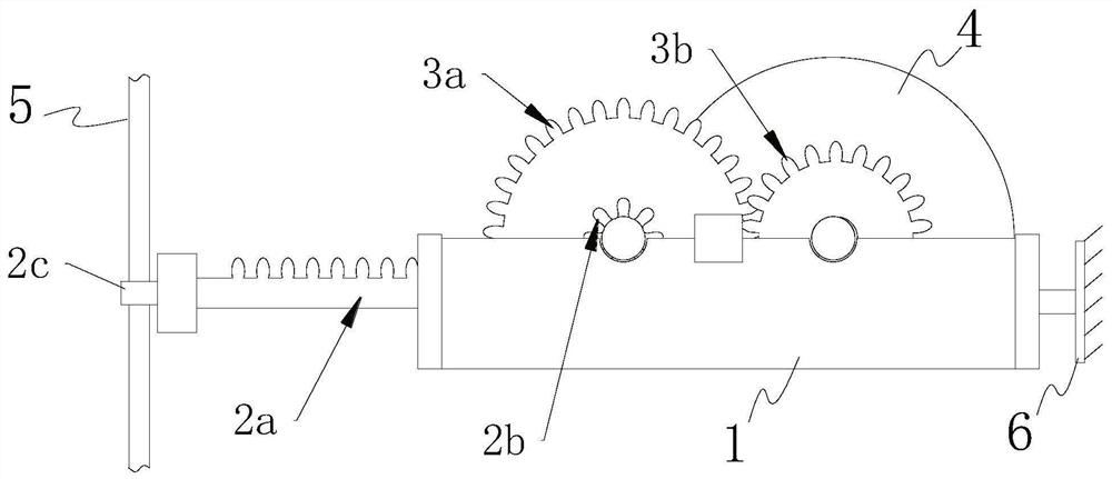
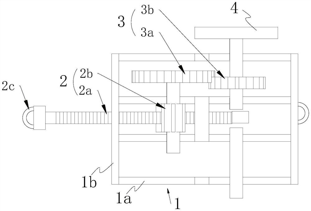
[0037] Such as figure 2 , 3 And 4, an adjustable inerter A, including a bracket 1, a flywheel 4 and a rotating drive mechanism 2 are installed on the bracket 1, and the two are connected by transmission. The rotation driving mechanism 2 is provided with a first connecting end for connecting with the vibrating member; the support 1 is provided with a second connecting end for connecting with the fixing member. The vibration of the vibrating part is transmitted to the flywheel 4 through the rotating drive mechanism 2 and the speed-increasing transmission mechanism to make it rotate, and the inertial force of the adjustable inerter container A reversely acts on the vibrating part to suppress its vibration.
[0038] In order to increase the inertial force of the adjustable inerter A and make its inertial force adjustable, a speed-increasing transmission mechanism is arranged between the rotating drive mechanism 2 and the flywheel 4, and the speed-increasing transmission mechanis...
Embodiment 2
[0057] A vibration damping method for the wind vibration of the circular tube member of the transmission tower, using the adjustable inerter described in Embodiment 1, comprising the following steps:
[0058] Step 1, understanding the on-site meteorological information, conducting on-site investigation and determining the circular tube member 5 that needs to be damped on the transmission tower B, and judging the vibration direction of the circular tube member 5;
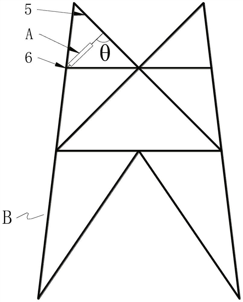
[0059] Step 2, select at least one iron tower fixing part 6 close to the round pipe member 5 for each of the round pipe members 5 on the transmission tower B, so as to connect the round pipe member 5 and the iron tower fixing part Install adjustable inerter A between 6;
[0060] Step three, such as figure 1 with 2 , to install the adjustable inerter container A: for the convenience of connection, the first connection end is provided with a pipe sleeve 2c, and the pipe sleeve 2c is sleeved on the circular pipe membe...
Embodiment 3
[0073] The ANSYS finite element model is used to study the vibration reduction effect of the above adjustable inerter. This simulation takes an UHV AC transmission line project as the research object, and selects the round pipe member 5, which frequently experiences breeze vibration in the UHV AC transmission line, for research. Its size parameters and constraints are shown in Table 1.
[0074] Table 1 Parameter table of circular tube components
[0075]
[0076] In this simulation, the relevant parameters of the adjustable inerter A are shown in Table 2. In the simulation tests 1-3, the value of the inerter characteristic b is only changed by changing the quality of the flywheel 4 . Under the corresponding conditions, the vibration amplitude of the circular tube member 5 is as follows Figure 5 shown. It can be seen that under the condition that the inerter is not installed, that is, b=0, the vibration amplitude of the circular tube member 5 is about 15mm after stabiliz...
PUM
 Abstract
Description
Claims
Application Information
 - R&D
- Intellectual Property
- Life Sciences
- Materials
- Tech Scout
- Unparalleled Data Quality
- Higher Quality Content
- 60% Fewer Hallucinations
Browse by: Latest US Patents, China's latest patents, Technical Efficacy Thesaurus, Application Domain, Technology Topic, Popular Technical Reports.
© 2025 PatSnap. All rights reserved.Legal|Privacy policy|Modern Slavery Act Transparency Statement|Sitemap|About US| Contact US: help@patsnap.com


