
Low-speed rotary sealing device
A rotary sealing, low-speed technology, applied in the direction of engine sealing, mechanical equipment, engine components, etc., can solve the problems of difficult replacement, low life, and no consideration of seal damage, etc., to increase the amount of interference, enhance the sealing effect, increase The effect of the sealing effect
- Summary
- Abstract
- Description
- Claims
- Application Information
AI Technical Summary
Problems solved by technology
Method used
Image

Examples
Embodiment Construction
[0012] The present invention will be described in further detail below in conjunction with the accompanying drawings and specific embodiments.
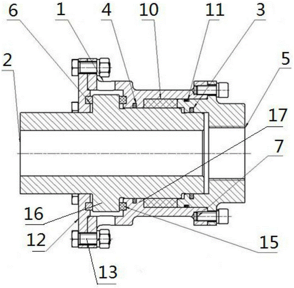
[0013] Such as figure 1 As shown, a low-speed rotary sealing device includes a housing 1 , a hollow rotating shaft 2 , a hollow fixed shaft 5 , an end cover 12 , a coarse sealing washer 15 and a main sealing ring 10 . The rotating shaft 2 and the fixed shaft 5 are coaxially arranged. The casing 1 is set on the rotating shaft 2 and the fixed shaft 5, and the end cover 12 is set on the outside of the rotating shaft 2. The inner end surface of the end cover 12 is pressed on one end surface of the boss I16 provided on the outer circle of the rotating shaft 2 and is connected with the outer surface of the casing 1. One end face is connected by bolt 13. A flange is arranged on the outer circle of the fixed shaft 5 , and the fixed shaft 5 is connected to the other end surface of the housing 1 through the flange and bolts 7 . Boss II 17 is...
PUM
 Abstract
Description
Claims
Application Information