Edge position detection device and edge position detection method

An edge position and detection device technology, applied in the field of edge position, can solve the problems of smaller gradient, lower contrast, and inability to detect edge position, etc.

Active Publication Date: 2018-06-08
DAINIPPON SCREEN MTG CO LTD
View PDF5 Cites 0 Cited by
  • Summary
  • Abstract
  • Description
  • Claims
  • Application Information

AI Technical Summary

Problems solved by technology

[0004] However, when an image for edge position detection as described above is acquired by a camera with a relatively low resolution, the gradient of the slope portion representing the edge in the luminance profile becomes small, and it becomes difficult to detect the edge position with high accuracy.
In addition, the contrast between the background area and the pattern unit between the pattern units arranged in close proximity decreases significantly, and there is a possibility that the edge position cannot be detected.

Method used


Image

  • Edge position detection device and edge position detection method
  • Edge position detection device and edge position detection method
  • Edge position detection device and edge position detection method

Examples


Embodiment Construction

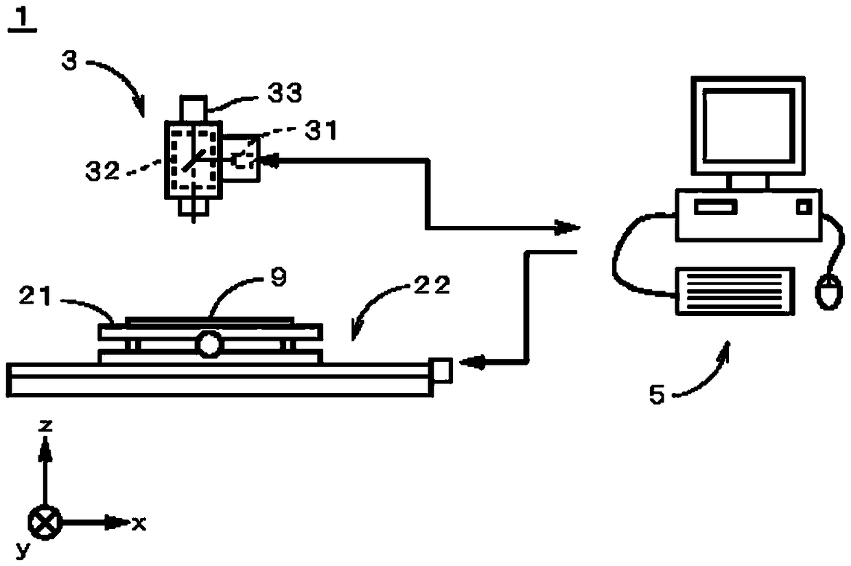
[0045] figure 1 It is a diagram showing a schematic configuration of a pattern measuring device 1 according to an embodiment of the present invention. The pattern measurement device 1 measures the width (namely, line width) of a linear pattern unit on a pattern formed on an object, that is, a semiconductor substrate, a glass substrate, or a printed circuit board (hereinafter, simply referred to as "substrate 9"). Automatic length measuring machine.

[0046] The pattern measuring device 1 has a table 21 , a table driving unit 22 , and an imaging unit 3 . The table 21 is used to hold the substrate 9 . The table drive unit 22 relatively moves the table 21 with respect to the imaging unit 3 . The table driving unit 22 is composed of a ball screw, a guide rail, a motor, and the like. The imaging unit 3 is disposed above the table 21 (ie, on the (+z) side), and captures image data of an inspection target region on the substrate 9 . The imaging unit 3 has an illumination unit 31...


PUM


Abstract

The invention provides an edge position detection device and method. A brightness profile in an inspection image representing a group of pattern units on a substrate is acquired by an edge position detection device (71). Next, for the luminance profile (71) having four concave portions (851) to (854) arranged alternately and three convex portions, while satisfying the constraint condition based on the design data of the pattern unit group, the four concave portions ( The four bell-shaped functions corresponding to (851) to (854) and the left-right symmetrical model function (72) synthesized by the three bell-shaped functions corresponding to the three convex parts are fitted. Then, a plurality of coefficients included in each bell function of the model function (72) are determined, and edge positions of linear pattern elements are obtained based on the model function (72). As a result, edge positions can be detected with high accuracy even in inspection images acquired with relatively low resolution.

Description

technical field [0001] The present invention relates to a technique for detecting the position of an edge included in a pattern unit group in an image representing the pattern unit group. Background technique [0002] Conventionally, at the manufacturing sites of semiconductor substrates, glass substrates, printed circuit boards, etc., the width (ie, line width) of the pattern elements is measured in an image representing the linear pattern elements on the object. In such measurement, it becomes important to detect the edge position of the pattern unit with good precision. [0003] For example, in the edge position detection device of JP-A-2012-73177 (Document 1), a method of obtaining the edge position of a pattern cell with good reproducibility is proposed. In this edge position detection means, the brightness profile in the width direction of the pattern unit on the image is acquired. Next, in this luminance profile, an object position group that is a part of a pluralit...

Claims


Application Information

Patent Timeline
Patent Type & Authority Patents(China)
IPC IPC(8): G01B11/02
Inventor 松村明
Owner DAINIPPON SCREEN MTG CO LTD
Why Eureka
Try Eureka