
Long-wave infrared optical mechanical athermalization lens and its compensation adjustment method

An infrared optics and lens technology, applied in optics, optical components, installation, etc., can solve problems such as image plane drift, optical system focal length change, and imaging quality degradation, and achieve the effect of compact structure, high resolution, and accurate precision

Active Publication Date: 2017-10-03
FUJIAN FORECAM OPTICS CO LTD
View PDF6 Cites 0 Cited by
  • Summary
  • Abstract
  • Description
  • Claims
  • Application Information

AI Technical Summary

Problems solved by technology

Because infrared optical materials and mechanical materials will produce thermal deformation when the temperature changes, the drastic change of working temperature will cause the focal length change of the optical system, the image surface is elegant, and the image quality is reduced.

Method used


Image

  • Long-wave infrared optical mechanical athermalization lens and its compensation adjustment method
  • Long-wave infrared optical mechanical athermalization lens and its compensation adjustment method

Examples


Embodiment Construction

[0019] The present invention will be further described below in conjunction with the accompanying drawings and specific embodiments.

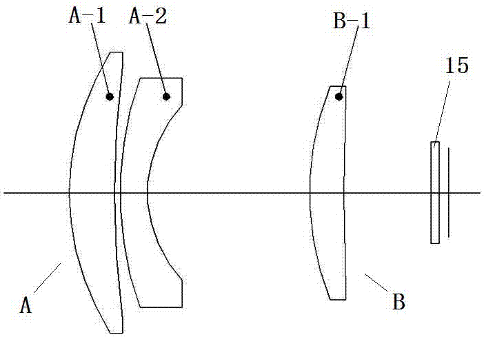
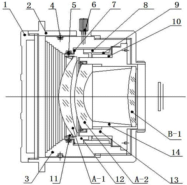
[0020] Such as Figure 1~2 As shown, a long-wave infrared optical-mechanical athermalization lens, in the optical system of the lens, along the incident direction of the light from left to right, the front group A of the lens group with negative refractive power and the lens with positive refractive power are sequentially arranged Group rear group B, a diaphragm 15 is arranged between the front group A and the rear group B, and the front group A includes a crescent-shaped lens A-1 and a negative crescent-shaped lens A-2 arranged in sequence from left to right; The rear group B includes a crescent lens B-1.

[0021] In this embodiment, the air gap between the crescent-shaped lens A-1 and the negative crescent-shaped lens A-2 in the front group A is 2 mm, and the air gap between the front group A and the rear group B is 21.21 mm. mm.

[0022] ...


PUM


Abstract

The invention relates to a long-wave infrared optical-mechanical athermal lens. The optical system of the lens is sequentially provided with a front group A of a lens group with a negative focal power and a rear group B of a lens group with a positive refractive power along the incident direction of light from left to right. The long-wave infrared optical mechanical athermalization lens has the advantages of large relative aperture, IP67 waterproof and dustproof, low distortion, and athermalization compensation. Through the design of mechanical athermalization, and the use of thermal expansion and contraction characteristics of materials and the application of compensation shrapnel, the athermalization design structure is simpler, and the overall product structure is smaller and clearer. In terms of meeting the user's requirements for product imaging performance, the structure is also more convenient for customers to use.

Description

technical field [0001] The invention relates to the technical field of optical lens devices, in particular to a long-wave infrared optical-mechanical athermalization lens and a compensation adjustment method thereof. Background technique [0002] With the rapid development of science and technology and the continuous development and maturity of uncooled detector technology, long-wave infrared uncooled optical systems have been widely used in military and civilian fields. Since infrared optical materials and mechanical materials will produce thermal deformation when the temperature changes, drastic changes in operating temperature will cause changes in the focal length of the optical system, image surface drift, and image quality degradation. In order to eliminate or reduce the impact of temperature changes on the imaging of the optical system, corresponding compensation techniques must be used to keep the focal length of the optical system constant within a large temperature...

Claims


Application Information

Patent Timeline
Patent Type & Authority Patents(China)
IPC IPC(8): G02B7/02
CPCG02B7/021G02B7/023G02B7/028
Inventor 刘涛郑勇强陈潇
Owner FUJIAN FORECAM OPTICS CO LTD
Learn More