an electrical connector

A technology for electrical connectors and connecting parts, which is applied in the direction of connection, parts and circuits of connecting devices, etc., can solve the problems of terminal elastic collapse, high cost of electrical connectors, and affecting the electrical performance of electrical connectors.

Active Publication Date: 2018-03-27
SHENZHEN DEREN ELECTRONICS
View PDF7 Cites 0 Cited by
  • Summary
  • Abstract
  • Description
  • Claims
  • Application Information

AI Technical Summary

Problems solved by technology

If one end of the terminal protrudes from the tongue plate, then in the process of plugging the electrical connectors, the tongue plate of one electrical connector will easily abut against the terminal of the other electrical connector, causing it to deform; If the board is flush with and protrudes from the plane of the tongue plate, then in the process of plugging the electrical connectors, the tongue plate of one electrical connector is also easy to abut against and lift up the terminals of the other electrical connector, causing it to deform. When deformed for a few times or for a long time, it is easy to cause the elasticity of the terminal to collapse, causing the terminal to kneel and affect the electrical performance of the electrical connector
[0004] In addition, in the original manufacturing process of electrical connectors, the insulating body includes first plastic and second plastic, the terminals are divided into first terminal and second terminal, the first terminal and the first plastic are embedded and molded, the second terminal and the second The second plastic embedded molding, and then the first plastic and the second plastic injection molding, wherein the process of the first terminal and the first plastic embedded molding and the second terminal and the second plastic embedded molding is very complicated and costly, which is easy to cause The cost of electrical connectors is too high

Method used


Image

  • an electrical connector
  • an electrical connector
  • an electrical connector

Examples


Embodiment Construction

[0027] A detailed description will be given below in conjunction with the accompanying drawings and embodiments.

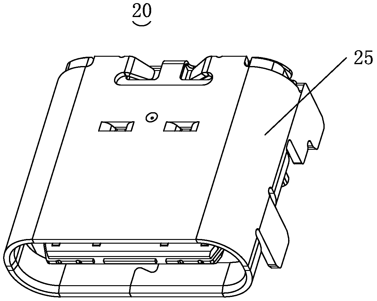
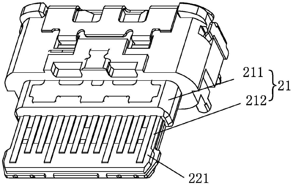
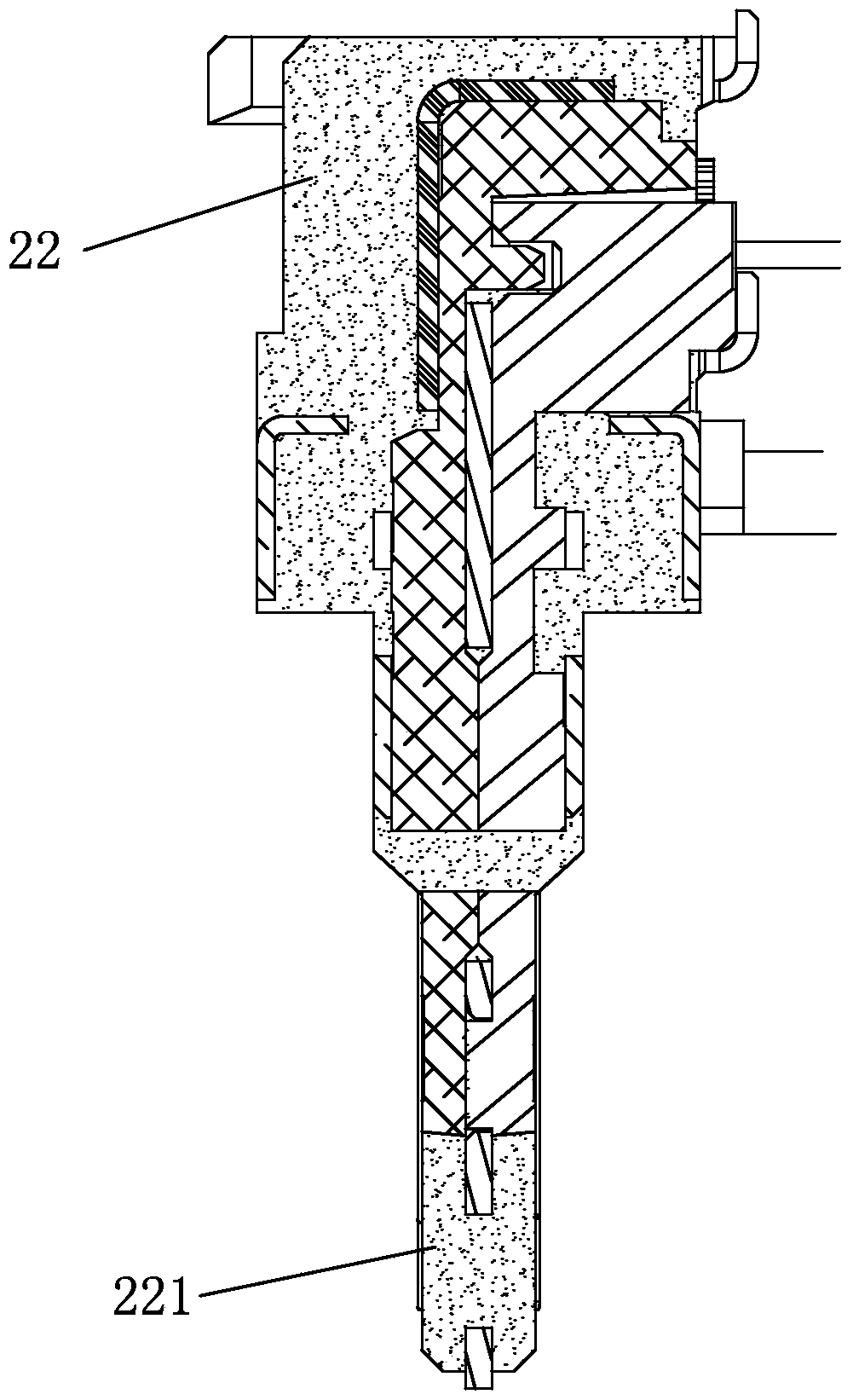
[0028] see Figure 1 to Figure 6 , the electrical connector 20 includes an insulating inner shell 21 , an insulating outer shell 22 , a first terminal 23 , a second terminal 24 and a metal shell 25 .

[0029] The insulating inner shell 21 includes a base 211 and a tongue 212 extending from the base 211 , wherein the tongue 212 is airtight. The insulating shell 22 wraps the outer surface of the insulating inner shell 21 , and the insulating shell 22 has a docking portion 221 extending toward the front end of the tongue plate 212 . It is worth noting that: the insulating shell 22 means that the plastic is heated and melted, and then coated on the surface of the insulating inner shell 21 to form a butt plate, while the airtight mentioned in this specification means that the insulating shell 22 does not extend to the tongue plate 212's interior. Further, the tongue...


PUM


Abstract

The invention discloses an electric connector which comprises an inner insulated casing, an outer insulated casing, first terminals and second terminals. The inner insulated casing comprises a base part and a tongue plate; the outer insulated casing wraps the external surface of the inner insulated casing, and includes a butt-joint portion which extends to the front end of the tongue plate; each first terminal comprises a first connection portion, a first front portion and a first back portion; and the second terminal comprises a second connection portion, a second front portion and a second back portion, both the second connection portion and the first connection portion are arranged in the base part, the first back portion and the second back portion are arranged at two surfaces, opposite to each other, of the tongue plate respectively, the first front portion and the second front portion are arranged at two surfaces, opposite to each other, of the butt-joint portion respectively, and the front end of the butt-joint portion is protruded out of the first and second front portions. When the electric connector is plugged with another connector, terminals of the other connector are guided to enter the tongue plate smoothly, and the other connector is prevented from jacking up the first or second front portion directly, causing deformation of the first or second portion, and influencing the electrical performance of the electric connector.

Description

technical field [0001] The invention relates to the technical field of connectors, in particular to an electrical connector. Background technique [0002] Electrical connectors, also known as circuit connectors, are conductor devices used to bridge two conductors on a circuit so that current or signals can flow from one conductor to another. It is widely used in various electrical circuits and plays the role of connecting or disconnecting current or signals. [0003] In the prior art, electrical connectors are usually used in pairs, and one electrical connector is mated with another electrical connector, so that one electrical connector communicates with the other electrical connector. The electrical connector includes an insulating body and a terminal, the insulating body includes a base and a tongue plate extending forward from the base, the terminal is fixed to the insulating body, and one end of the terminal is flush with the tongue plate and protrudes from the plane of...

Claims


Application Information

Patent Timeline
Patent Type & Authority Patents(China)
IPC IPC(8): H01R13/631
CPCH01R13/631
Inventor 陈正一
Owner SHENZHEN DEREN ELECTRONICS
Why Eureka
Try Eureka