
Injection molding method for preventing large-area metal part rubber coating deformation, injection mold and large-area metal part rubber coating product

A large-area metal and injection mold technology, applied in the direction of coating, etc., can solve the problems of electrical insulation, voltage resistance and electrical performance that cannot meet customer standards, uneven product thickness, and affect the assembly of finished products, so as to prevent rubber coating Effects of uneven meat thickness, reduction of deformation, and improvement of electrical performance

Pending Publication Date: 2021-04-30
瑞晟新能源科技(广东)有限公司
View PDF2 Cites 0 Cited by
  • Summary
  • Abstract
  • Description
  • Claims
  • Application Information

AI Technical Summary

Problems solved by technology

Due to the soft metal materials such as copper and aluminum, they are easy to deform during the injection molding process in the mold cavity, especially for large-area hardware parts with an area of ​​more than 600 square millimeters and a thickness of about 2.5mm, the injection molding in the mold is seriously deformed. As a result, the thickness of the product's rubber coating is uneven after injection molding, which not only affects the assembly of the finished product, but also directly causes the electrical performance of the product such as electrical insulation and voltage resistance to fail to meet customer standards

Method used


Image

  • Injection molding method for preventing large-area metal part rubber coating deformation, injection mold and large-area metal part rubber coating product
  • Injection molding method for preventing large-area metal part rubber coating deformation, injection mold and large-area metal part rubber coating product
  • Injection molding method for preventing large-area metal part rubber coating deformation, injection mold and large-area metal part rubber coating product

Examples


Embodiment Construction

[0051] The implementation of the present invention will be described in detail below in conjunction with the accompanying drawings. The accompanying drawings are only for reference and description, and do not constitute a limitation to the protection scope of the present invention.

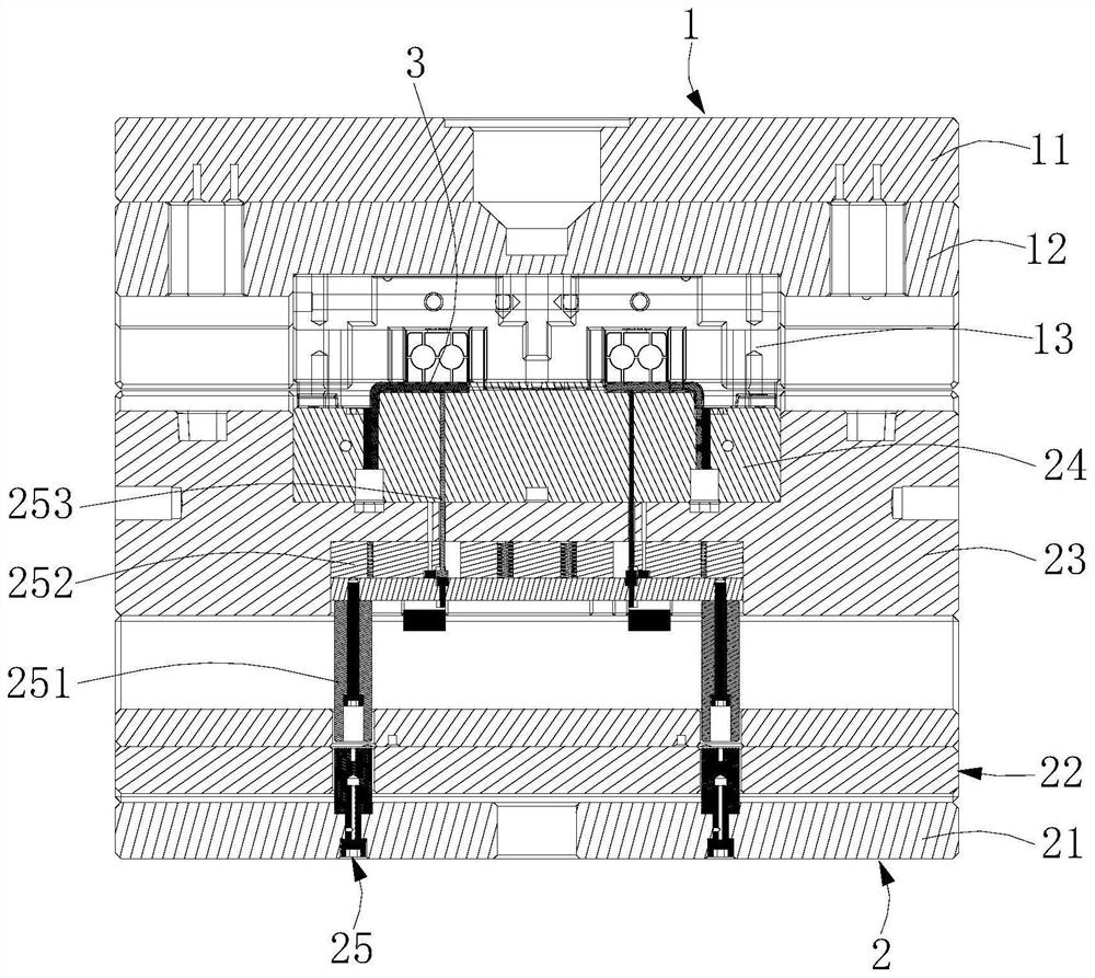
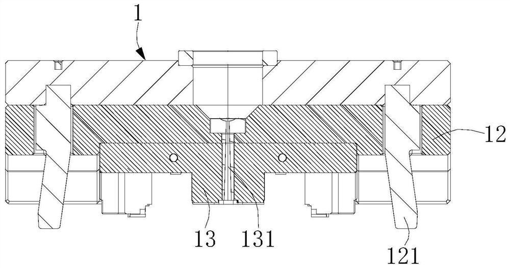
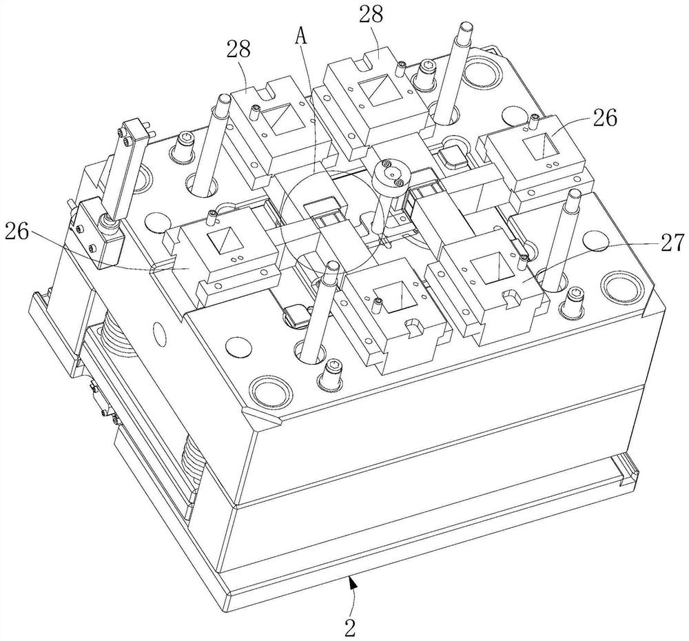
[0052] refer to Figure 1 to Figure 8 , an injection molding method for preventing deformation of large-area metal parts, comprising the following steps:

[0053] Step 1. Determine the stressed area 411 of the metal part 41 through mold flow analysis;

[0054] Step 11, open a plurality of glue passing holes 412 and a plurality of positioning holes 413 at intervals in the stressed area 411 of the metal part 41, so that the plurality of glue passing holes 412 are located at the edge of the metal part 41, and the plurality of positioning holes 413 and the injection mold A plurality of supporting pillars 253 in one-to-one correspondence;

[0055] Step 2. Put the metal part 41 into a fixed position i...


PUM


Abstract

The invention belongs to the technical field of injection molds, and particularly discloses an injection molding method for preventing large-area metal part rubber coating deformation, an injection mold and a large-area metal part rubber coating product. The injection molding method comprises the following steps of, 1, determining a stress area of a metal part; 2, putting the metal part into a cavity of the injection mold; 3, carrying out die assembly; 4, controlling supporting columns of the injection mold to move, so that the supporting columns extend into the cavity and abuts against the reverse side of the stress area of the metal part; 5, injecting molten plastic into the cavity; 6, carrying out injection molding pressure maintaining, meanwhile, withdrawing the supporting columns, forming supporting vacant positions by the supporting columns on the metal part, and filling supporting vacant positions with molten plastic under the action of injection molding pressure maintaining; and 7, carrying cooling and mold opening, and taking out a molded rubber-coated product. By supporting the reverse side of the stress area of the metal part in the mold, the defects of injection molding deformation and non-uniform rubber coating thickness of the metal part are prevented.

Description

technical field [0001] The invention belongs to the technical field of injection moulds, and in particular relates to an injection molding method for preventing deformation of large-area metal parts with rubber coating, an injection mold and a large-area metal parts rubber-coated product. Background technique [0002] Insert molding refers to a molding method in which a pre-prepared insert of different materials is placed in a mold and then molten material is injected, and the molten material is bonded with the insert to solidify to form an integrated product. [0003] Most of the in-mold inserts in the injection molding industry are small hardware, nuts, and cylindrical hardware. Due to the soft hardware materials such as copper and aluminum, they are easy to deform during the injection molding process in the mold cavity, especially for large-area hardware parts with an area of ​​more than 600 square millimeters and a thickness of about 2.5mm, the injection molding in the m...

Claims


Application Information

Patent Timeline
Patent Type & Authority Applications(China)
IPC IPC(8): B29C45/14B29C45/33
CPCB29C45/14778B29C45/14836B29C45/33
Inventor 戴柏名尹飞飞
Owner 瑞晟新能源科技(广东)有限公司
Learn More