
Plastic-encapsulated branch device and assembling process thereof

A technology of splitters and branch cables, which is applied in the assembly/disassembly of contacts, coupling devices, parts of connection devices, etc. It can solve problems such as the impact of withstand voltage levels, low reliability, and pollution of the client site environment, and achieve The production process is simple and reliable, the electrical performance is better, and the customer is convenient to use.

Pending Publication Date: 2019-12-31
成都合众宝根电子有限公司
View PDF0 Cites 0 Cited by
  • Summary
  • Abstract
  • Description
  • Claims
  • Application Information

AI Technical Summary

Problems solved by technology

[0003] Usually, the insulating shell of the splitter adopts the combination method of machine-added parts. This method needs to be constructed and assembled on the client site. The construction period of the client site is long and the installation cost is high. Gap, related gaps have the risk of high-voltage breakdown in a high-voltage environment, and the withstand voltage level will be affected in the case of the same volume
The power-taking mode of the shielding layer connection is to tightly wrap the external copper wires outside the shielding layer copper wires to bind them well, then solder the tin, and then solder the branch cables 17 on it. This scheme is complicated to operate, cumbersome and reliable. sex is also lower

Method used


Image

  • Plastic-encapsulated branch device and assembling process thereof
  • Plastic-encapsulated branch device and assembling process thereof
  • Plastic-encapsulated branch device and assembling process thereof

Examples


Embodiment Construction

[0035] The specific embodiments of the present invention are described below so that those skilled in the art can understand the present invention, but it should be clear that the present invention is not limited to the scope of the specific embodiments. For those of ordinary skill in the art, as long as various changes Within the spirit and scope of the present invention defined and determined by the appended claims, these changes are obvious, and all inventions and creations using the concept of the present invention are included in the protection list.

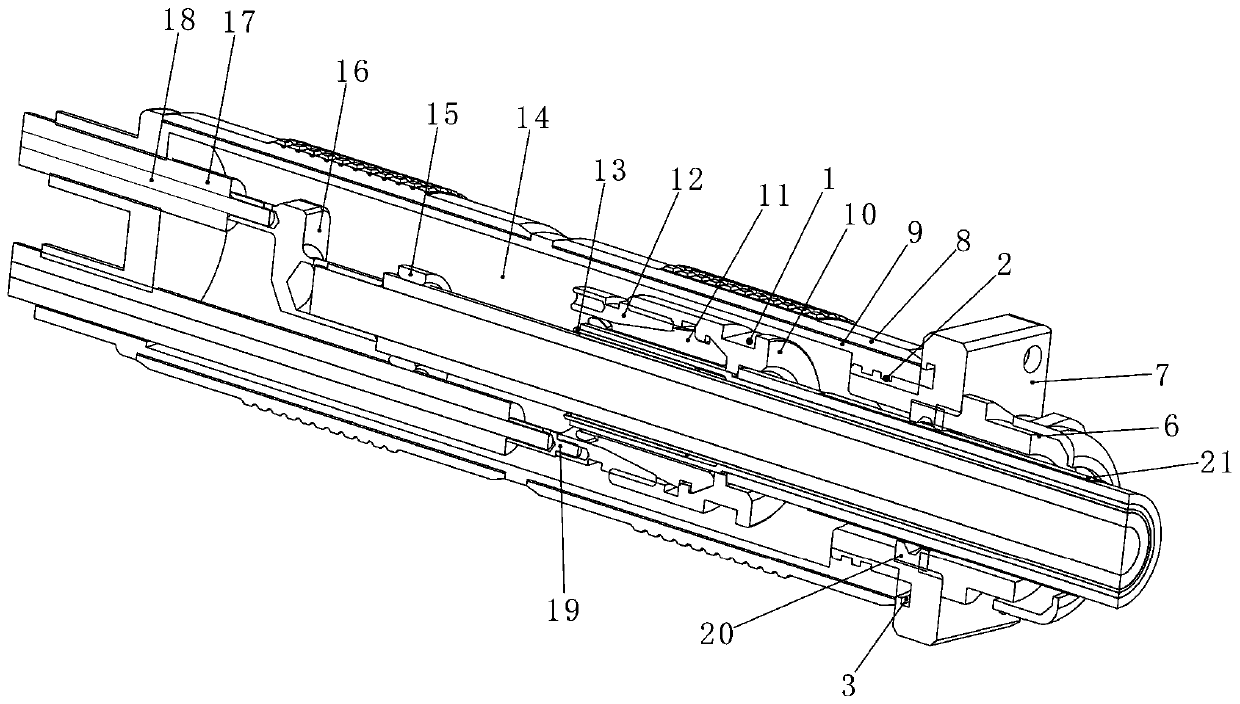
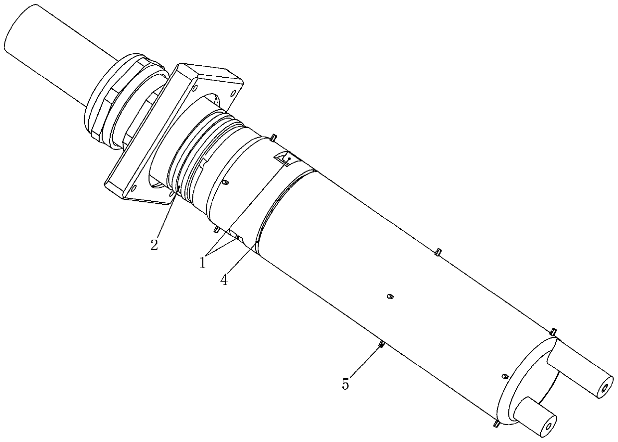
[0036] Such as figure 1 As shown, the plastic-encapsulated branch includes a lock nut 10, and a shuttle-shaped collet 11 is arranged inside the lock nut 10. The spring collet 11 and the lock nut 10 are locked by a tapered sleeve 12, and the spring collet 11 is locked. Installed in the lock nut 10, the tapered sleeve 12 is connected with the branch cable 17 through the straight terminal 19, the lock nut 10 is wrapped with th...


PUM


Abstract

The invention discloses a plastic-encapsulated branch device which comprises a locking nut. A shuttle-shaped spring chuck is arranged in the locking nut. The spring chuck and the locking nut are locked through a tapered sleeve. The tapered sleeve is connected with a branch cable through a straight terminal. A first filling plastic layer wraps outside the locking nut. The first filling plastic layer is internally provided with a Z-shaped terminal. One end of the Z-shaped terminal is coaxial with the locking nut, and the other end is connected with the branch cable. The first filling plastic layer is wrapped by a second filling plastic layer. One end of the first filling plastic layer and one end of the second filling plastic layer are fixedly connected with a flange plate and a cable gland.The assembling process comprises steps S1-S9. The device is fixed on the customer's mechanism through the flange plate between the client sides so that the construction is convenient and use is convenient for the customer; the forming process completely fills the gaps of the parts, and the electrical performance is better under the same volume; and the clamping process is adopted to realize the power extraction of the shielding layer, and the production process is simple and reliable.

Description

technical field [0001] The invention relates to the technical field of electrical connectors, in particular to a plastic-encapsulated splitter and an assembly process thereof. Background technique [0002] The function of the cable splitter is to separate the shielding layer and the inner conductor layer of the high-voltage coaxial cable from the same cable into two independent cables, so as to facilitate the connection with the corresponding device, so that the shielding layer and the inner conductor form a complete circuit The circuit realizes the input and output of current. [0003] Usually, the insulating shell of the splitter adopts the combination method of machine-added parts. This method needs to be constructed and assembled on the client site. The construction period of the client site is long and the installation cost is high. Gap, related gaps have the risk of high-voltage breakdown in a high-voltage environment, and the withstand voltage level will be affected ...

Claims


Application Information

Patent Timeline
IPC IPC(8): H01R13/02H01R13/40H01R13/405H01R13/46H01R13/502H01R13/504H01R4/50H01R43/00H01R43/20
CPCH01R4/5016H01R13/02H01R13/40H01R13/405H01R13/465H01R13/502H01R13/504H01R43/00H01R43/20
Inventor 陈学军
Owner 成都合众宝根电子有限公司
Learn More