Coaxial load with radial radiating structure

A technology of heat dissipation structure and coaxial load, applied in electrical components, circuits, waveguide devices, etc., can solve the problems of high product cost, increased cumulative error of product mechanical parameters, small competitive advantage, etc., to achieve product consistency guarantee , The effect of reducing raw material waste and shortening processing cycle

Inactive Publication Date: 2012-02-15
合肥佰特微波技术有限公司
View PDF4 Cites 0 Cited by
  • Summary
  • Abstract
  • Description
  • Claims
  • Application Information

AI Technical Summary

Problems solved by technology

There are four disadvantages in this method: first, the product cost is high, the complete machining heat dissipation shell is difficult to process, the processing cycle is long, the consumption of raw materials is large, and the competitive advantage in the market is small; the second is that this kind of coaxial load assembly The production efficiency is low, and the assembly of many parts brings a certain degree of difficulty, and once the assembly is completed, it is very difficult to disassemble; the third is the poor electrical performance index of the coaxial load. The coaxial load structure composed of many parts is Errors in various aspects such as machining errors, random errors, and assembly errors will inevitably increase the cumulative error of the product’s mechanical parameters, resulting in poor electrical performance of the product; the fourth is the poor mechanical performance of the coaxial load, which is fixed and connected by many parts through screws. The combined coaxial load structure, the structural parts are prone to mechanical fatigue failure, resulting in unstable mechanical performance indicators of the coaxial load

Method used


Image

  • Coaxial load with radial radiating structure
  • Coaxial load with radial radiating structure
  • Coaxial load with radial radiating structure

Examples


Embodiment

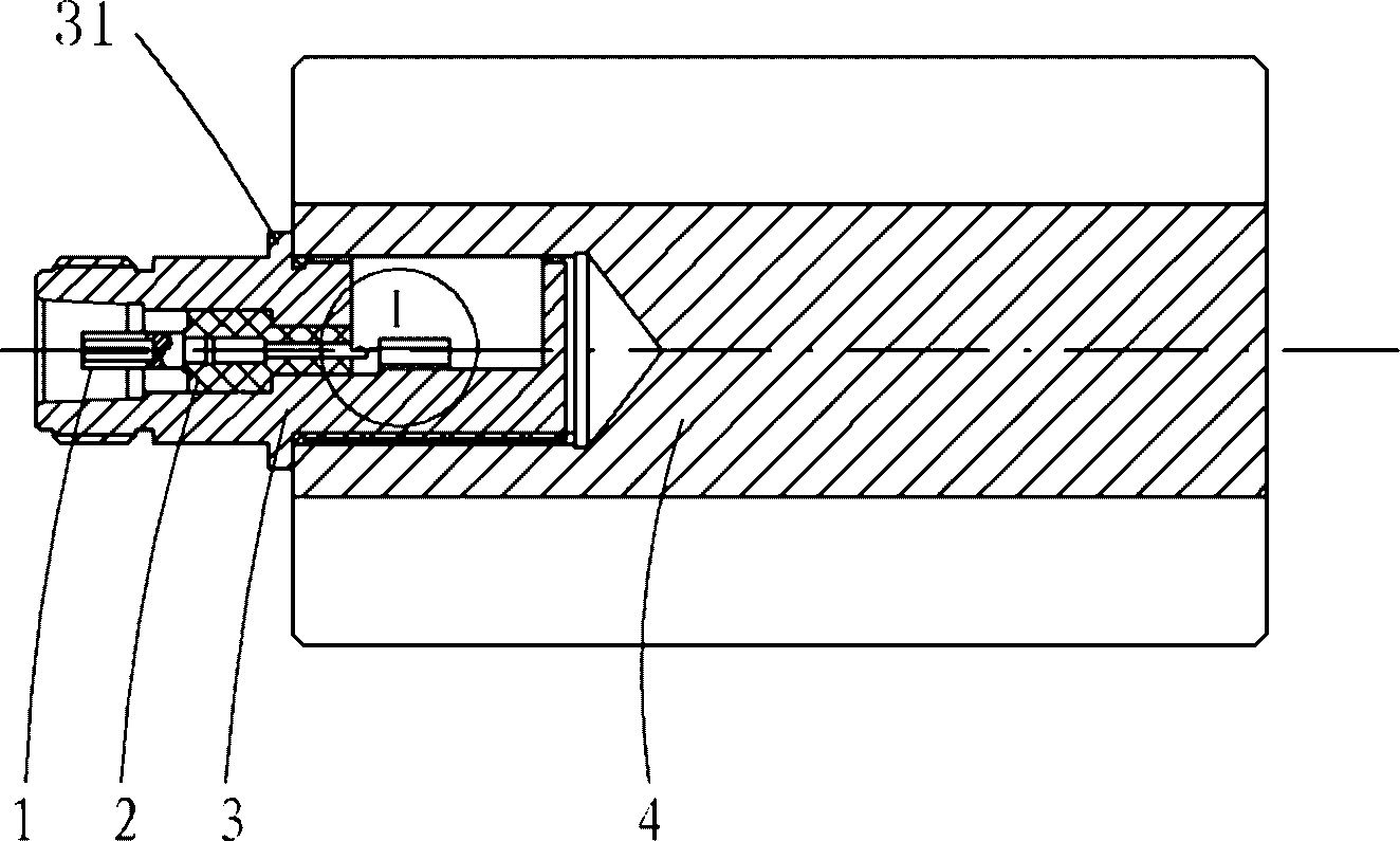
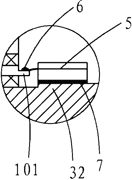
[0017] Example: see Figure 1A-Figure 1C , the coaxial load of this embodiment, its heat dissipation part is a radiator with a radial heat dissipation structure, the coaxial load of this embodiment includes a connector and a radial radiator 4 threaded with the connector, and the connector is from the inside to the The outer part is composed of an inner conductor 1, an insulating medium 2 and an outer conductor 3 arranged coaxially. The tail of the outer conductor 3 is screwed into the inner hole of the end face of the radial radiator 4, and an absorber is fixedly connected in the inner cavity of the tail of the outer conductor 3. The resistance 5 and the absorption resistance 5 are welded and fixed to the welding platform 101 provided at the end of the inner conductor 1 .

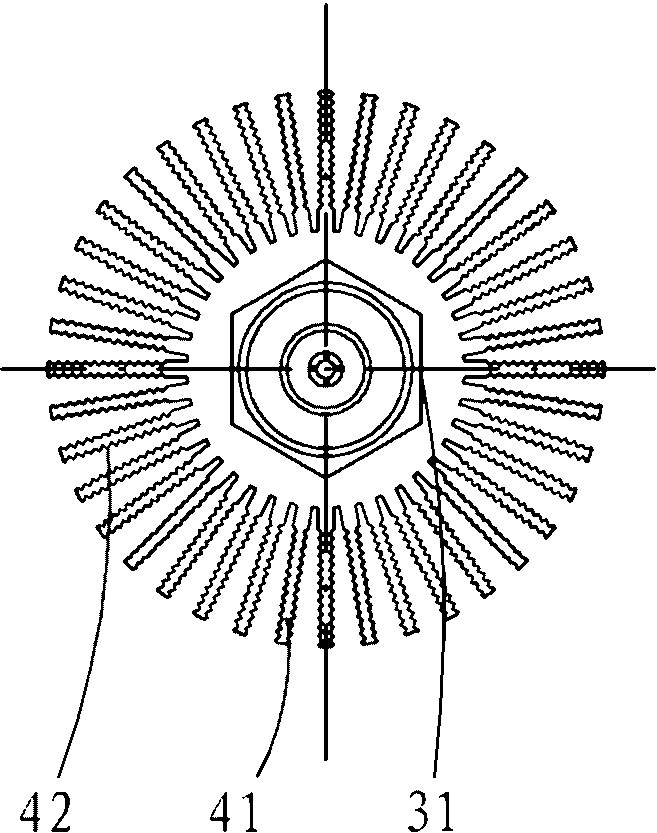
[0018] In specific settings, Figure 1B As shown, the radial radiator 4 has a cylindrical shape as a whole, and a plurality of cooling fins 41 are arranged on the outer circumference of the radiator, and e...


PUM


Abstract

The invention discloses a coaxial load with a radial radiating structure. The coaxial load comprises a connector and a radial radiator in threaded connection with the connector, wherein the connector is formed by an inner conductor, an insulating medium and an outer conductor which are coaxially arranged from inside to outside; the tail of the outer conductor is in threaded connection with the inner hole of the end face of the radial radiator; an absorbing resistor is fixedly connected in the cavity of the tail of the outer conductor; and the absorbing resistor is fixedly welded together with a welding platform at the tail of the inner conductor. The coaxial load can realize rapid processing, has a concise structure, is simple and reliable in connection, has good price comparability and superior and more stable electrical property and is suitable for mass production.

Description

Technical field: [0001] The invention relates to a coaxial load with a radial heat dissipation structure, which is a coaxial load suitable for microwave communication systems with different connector types such as N type and 7 / 16 type that meet the industry standard of coaxial connectors. Background technique: [0002] At present, for coaxial loads, the connector and the heat sink base are generally connected by screws, and the power resistor is fastened to the heat sink base by screws; a printed board is used for transition between the power resistor and the inner conductor of the connector, and then Welding; heat dissipation shell is machined heat dissipation shell with round fins. Such as figure 2 As shown, specifically, the jack 8 of the connector (connected to the inner conductor), the shell 13 and the insulator 9 are assembled to form a connector; the printed board 10 is fastened to the heat dissipation shell base 12 by screws, and the The power resistor 11 is fasten...

Claims


Application Information

Patent Timeline
Patent Type & Authority Applications(China)
IPC IPC(8): H01P1/26
Inventor 齐磊张祝松
Owner 合肥佰特微波技术有限公司
Why Eureka
Try Eureka