

Corn threshing machine
A technology for thresher and corn, applied in threshing equipment, agricultural machinery and implements, applications, etc., can solve the problems of low threshing rate, affecting threshing efficiency, etc. Effect
Inactive Publication Date: 2016-03-16
CHONGQING CHANGHUI ANIMAL HUSBANDRY CO LTD
View PDF7 Cites 0 Cited by
- Summary
- Abstract
- Description
- Claims
- Application Information
AI Technical Summary
Problems solved by technology
However, there is still a low threshing rate, and usually a second threshing is required to thresh all the corn kernels on the corn cob, which affects the threshing efficiency. On the other hand, the power device installed on the threshing machine cannot be adjusted. make it limited
Method used
View moreImage
Smart ImageViewing Examples

Examples
specific Embodiment approach
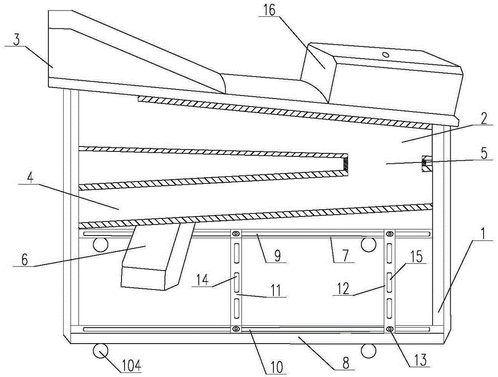
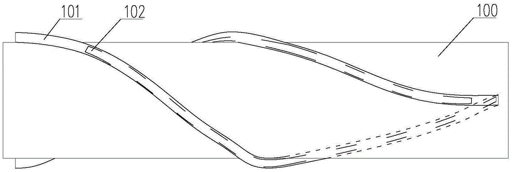
[0018] When in use, put the corn cobs from the first feeding port 3, the threshing drum 100 in the first threshing bin 2 starts to rotate, the corn cobs are threshed in the first threshing bin 2, and then the corn cobs pass through the corn threshing bin 5 into the second threshing bin 4 for the second threshing. After the threshing is completed, the corn kernels fall into the container through the splash guard 6.
Login to View More PUM
 Abstract
The invention discloses a corn threshing machine comprising a machine frame and a first threshing chamber arranged on the machine frame in a front-high rear-low manner; a threshing cylinder is arranged in the first threshing chamber; a first feeding port is arranged above the front end of the first threshing chamber, and the rear end of the first threshing chamber is provided with a first discharge port; the machine frame is provided with a second threshing chamber arranged right below the first threshing chamber; the second threshing chamber is arranged on the machine frame in a front-low rear-high manner; the high end of the second threshing chamber is the second feeding port; the second feeding port is connected with the first discharge port through a corn threshing connecting chamber; the low end of the second threshing chamber is provided with a second discharge port having an anti-splashing device. The threshing machine can improve corn threshing rate, is low in reconstruction cost, and can improve threshing speed.
Description
technical field [0001] The invention relates to an agricultural equipment, in particular to a corn thresher. Background technique [0002] The existing corn thresher comprises a threshing drum, a threshing bin and a frame, and the drum of the corn thresher is installed in the threshing bin and can rotate relative to the threshing bin. In order to improve the threshing efficiency, the drum of the existing threshing machine is generally provided with threshing ribs, and when the drum rotates, the corn kernels are separated from the corn cob under the action of the threshing ribs. However, there is still a low threshing rate, and usually a second threshing is required to thresh all the corn kernels on the corn cob, which affects the threshing efficiency. On the other hand, the power unit installed on the thresher cannot be adjusted. make it limited. [0003] Therefore those skilled in the art are devoted to developing a kind of corn thresher that improves cleaning rate. Con...
Claims
Login to View More Application Information
Patent Timeline
 Patent Type & AuthorityApplications(China)
IPC IPC(8): A01F11/06A01F12/20
CPCA01F11/06A01F12/20
Inventor刘仕雄徐玲玲
OwnerCHONGQING CHANGHUI ANIMAL HUSBANDRY CO LTD