ultrasonic cleaner

An ultrasonic cleaning machine technology, applied in the field of ultrasonic cleaning, can solve the problems of low work efficiency and high labor intensity, and achieve the effects of short cleaning time, high electro-acoustic efficiency and low energy consumption

Inactive Publication Date: 2011-12-14
湘潭大众整流器制造有限公司
View PDF8 Cites 17 Cited by
  • Summary
  • Abstract
  • Description
  • Claims
  • Application Information

AI Technical Summary

Problems solved by technology

The number of cathode plates used for electrolysis in each electrolysis workshop can reach thousands of pieces per day, and the weight of each cathode plate is about 6 kilograms. Therefore, the plate washers who clean the semi-mechanized equipment in the electrolysis workshop have to clean and pick up the finished products every day. Thousands of cathode plates also have the defects of high labor intensity and low work efficiency

Method used


Image

  • ultrasonic cleaner
  • ultrasonic cleaner
  • ultrasonic cleaner

Examples


Embodiment Construction

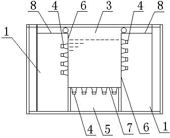
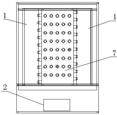
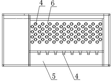
[0014] see Figure 1 to Figure 3 , an ultrasonic cleaning machine, which includes a cleaning pool 3, vibrator chambers 1 are respectively arranged on both sides of the cleaning pool 3, the cleaning pool 3 and the vibrator chamber 1 are isolated by side partitions 6, and several vibrators 4 are arranged on the outer wall of the side partitions 6, The bottom vibrator chamber 5 is arranged under the bottom partition 7 of the cleaning tank 3 , and several vibrators 4 are arranged on the bottom surface of the bottom partition 7 ; all vibrators 4 are connected to the ultrasonic generator 2 . The tops of the two vibrator chambers 1 are respectively provided with cover plates 8 . Vibrator 4 is also called an ultrasonic transducer.

[0015] The working principle of the present invention: fill the cleaning tank 3 with cleaning liquid, put a number of electrolytic cathode plates into the cleaning tank 3 stably by a crane, put the electrolytic negative plates upright into the cleaning ta...


PUM


Abstract

The invention discloses an ultrasonic cleaning machine, which comprises a cleaning tank, vibrator chambers are respectively arranged on both sides of the cleaning tank, the cleaning tank and the vibrator chamber are separated by side partitions, several vibrators are respectively arranged on the outer walls of the partitions on both sides, the cleaning tank A bottom vibrator chamber is arranged under the bottom partition, and several vibrators are arranged on the bottom surface of the bottom partition; all the vibrators are connected to the ultrasonic generator. The invention overcomes the defects of high labor intensity and low work efficiency of the existing manual and semi-mechanized cleaning of electrolysis cathode plates, and is suitable for batch cleaning of electrolysis cathode plates and other similar items.

Description

technical field [0001] The invention relates to an ultrasonic cleaning, in particular to an ultrasonic cleaning machine for cleaning electrolytic manganese cathode plates. Background technique [0002] At present, most of the cleaning of electrolytic cathode plates in electrolytic manganese plants is done manually by workers, and very few enterprises use semi-mechanized manual cleaning. When manually scrubbing the electrolytic cathode plate, the labor intensity of the workers is very high. Whether it is freezing cold in winter or hot and humid in summer, the workers’ hands are in contact with the cleaning solution for a long time, which will cause damage to the workers’ bodies. Moreover, the manual cleaning of the electrolytic cathode plate is slow, inefficient, and consumes a lot of cleaning solution. During semi-mechanized cleaning, the cathode plates are manually sent to the cleaning equipment one by one, and the cathode plates are manually lifted out of the cleaning equ...

Claims


Application Information

Patent Timeline
Patent Type & Authority Applications(China)
IPC IPC(8): B08B3/12
Inventor 杨颂初
Owner 湘潭大众整流器制造有限公司
Why Eureka
Try Eureka