Eureka AIR delivers breakthrough ideas for toughest innovation challenges, trusted by R&D personnel around the world.

A fully automatic mold moving and pushing device

A pusher device and fully automatic technology, which is applied in the field of hydraulic presses, can solve the problems of high labor intensity in feeding and picking up parts, large one-time investment, and increased costs, and achieve the effects of improving labor efficiency, low cost, and reducing labor intensity

Active Publication Date: 2017-07-28
YANGZHOU METALLURGICAL MACHINERY
View PDF8 Cites 0 Cited by
  • Summary
  • Abstract
  • Description
  • Claims
  • Application Information

AI Technical Summary

Problems solved by technology

[0002] Since the ordinary hydraulic press is not equipped with a fully automatic mold-moving and pushing device, the upper half of the mold (hereinafter referred to as the upper mold) is fixed on the slider of the hydraulic press, and the lower half of the mold (hereinafter referred to as the lower mold) is fixed on the working table of the hydraulic press. For heavy workpieces, it is impossible to use conventional lifting devices to feed and pick up parts in the working area of ​​the hydraulic press. Manual work is used, and the labor intensity of feeding and picking up parts is relatively high; when using manipulators, the one-time investment is large, which increases the cost.

Method used


Image

  • A fully automatic mold moving and pushing device
  • A fully automatic mold moving and pushing device
  • A fully automatic mold moving and pushing device

Examples


Embodiment Construction

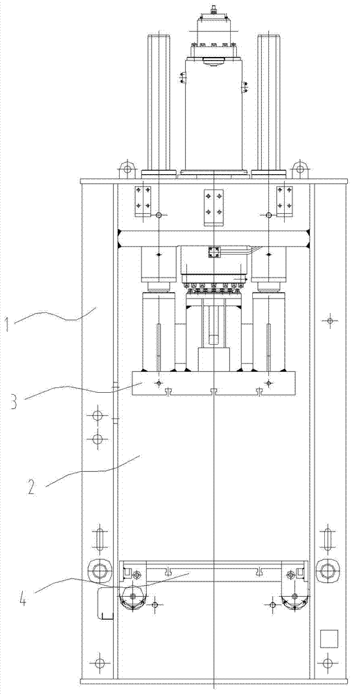
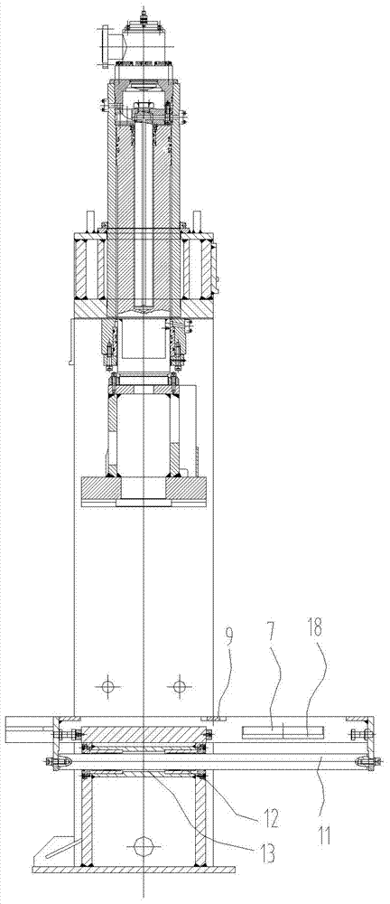
[0028] The present invention as Figure 1-8 As shown, the die-moving pushing device is arranged on a hydraulic press, and the hydraulic press includes a fuselage 1, a cavity body 2 is provided in the middle of the fuselage, and a slide block 3 is provided on the top of the cavity body 2, The lower part is provided with a workbench 4, the slider is used to connect the upper mold, and the workbench is used to place the lower mold 5;

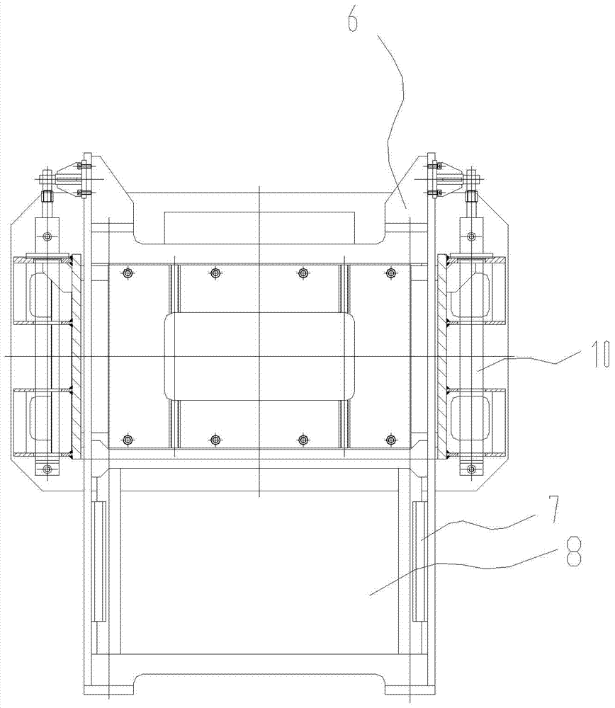
[0029] The mold-moving and pushing device includes a mold-moving and pushing bracket 6 and a mold lifter 7, and the mold-moving and pushing bracket 6 is horizontally and movably connected to the bottom of the cavity body 2, and the mold-moving and pushing bracket 6 has a sliding hole 8. A push rod 9 is provided at the middle top of the slide hole, the bottom surface of the push rod 9 is higher than the top surface of the workbench 4, and the workbench 4 is located in the slide hole 8, the The mold lifter 7 is arranged on the mold-moving push mater...


PUM


Abstract

The invention discloses a full-automatic die moving and pushing device and provides a full-automatic die moving and pushing device which is simple in structure and capable of conveniently realizing a die moving action and improving the working reliability. The die moving and pushing device is arranged on a hydraulic machine; the hydraulic machine comprises a machine body; a cavity is arranged in the middle of the machine body; a slide block is arranged at the upper part of the cavity, and a workbench is arranged at the lower part of the cavity; the slide block is connected with an upper die; the workbench is used for placing a lower die; the die moving and pushing device comprises a die moving and pushing support and die lifters; the die moving and pushing support is horizontally and movably connected to the lower part of the cavity; a sliding hole is formed in the die moving and pushing support; a push rod is arranged at the top of the middle of the sliding hole; the bottom of the push rod is higher than the top of the workbench; the workbench is located in the sliding hole; the die lifters are arranged on the die moving and pushing support and are located at the outer side of the push rod and at two ends of the workbench. By using the full-automatic die moving and pushing device, the labor efficiency is increased, the cost is low, and workpieces are not needed to be fetched manually.

Description

technical field [0001] The invention relates to a hydraulic press, in particular to a fully automatic die-moving and material-moving device for the hydraulic press. Background technique [0002] Since the ordinary hydraulic press is not equipped with a fully automatic mold-moving and pushing device, the upper half of the mold (hereinafter referred to as the upper mold) is fixed on the slider of the hydraulic press, and the lower half of the mold (hereinafter referred to as the lower mold) is fixed on the working table of the hydraulic press. For heavy workpieces, conventional lifting devices cannot be used to feed and pick up parts in the working area of ​​the hydraulic press. Manual work is used, and the labor intensity of feeding and picking up parts is relatively high; manipulators are used for operations, and the one-time investment is large, which increases the cost. Contents of the invention [0003] Aiming at the above problems, the present invention provides a full...

Claims


Application Information

Patent Timeline
Patent Type & Authority Patents(China)
IPC IPC(8): B30B15/30B30B15/32
CPCB30B15/30B30B15/32
Inventor 潘晓慧胡明杰刘飞
Owner YANGZHOU METALLURGICAL MACHINERY
Why Eureka
Eureka Blog
Learn More