Image forming device and its paper discharge mechanism

A paper discharge and paper discharge technology, which is applied in the field of image forming devices and paper discharge mechanisms, can solve the problems of paper jams and low productivity, and achieve the effect of reducing paper jams and high productivity

Active Publication Date: 2017-07-18
KONICA MINOLTA TECH DEV WUXI
View PDF5 Cites 0 Cited by
  • Summary
  • Abstract
  • Description
  • Claims
  • Application Information

AI Technical Summary

Problems solved by technology

[0012] The problem to be solved by the present invention is: the paper discharge mechanism of the existing image forming device cannot solve the problems of paper jam and low productivity at the same time

Method used


Image

  • Image forming device and its paper discharge mechanism
  • Image forming device and its paper discharge mechanism
  • Image forming device and its paper discharge mechanism

Examples


no. 1 example

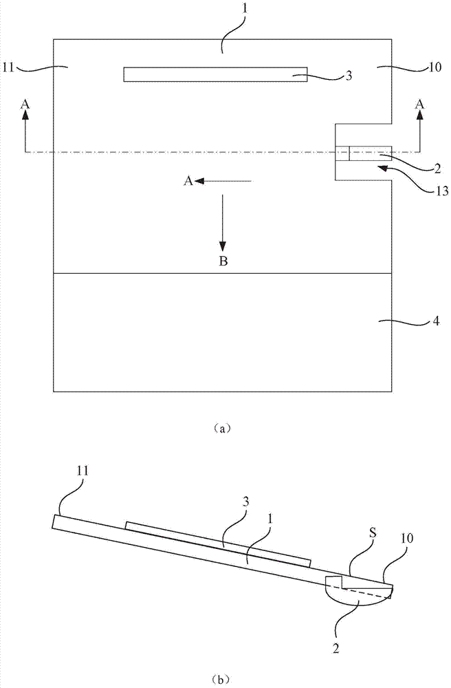
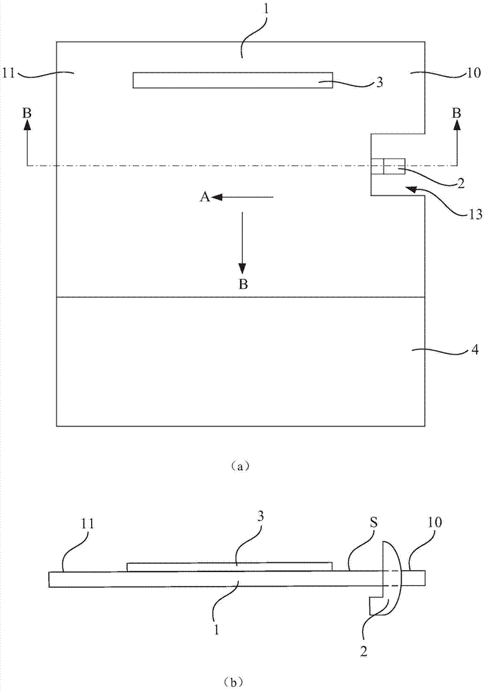
[0052] refer to image 3 , Figure 5 As shown, the paper discharge mechanism of the present embodiment includes:

[0053] The tray 10 is used to carry the paper P discharged along the discharge direction A from the paper outlet (not shown) of the image forming apparatus. In the post-processing state, the tray 10 is located at a horizontal position, combined with Figure 7 As shown in , the tray 10 is in the initial inclined position in the paper discharge state;

[0054] The adjustment part 20 is linked with the tray 10 and used to adjust the tray 10 to the horizontal position and the initial inclined position;

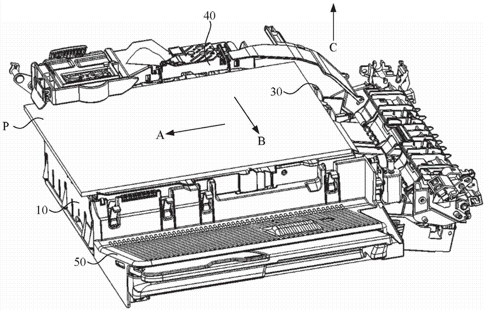
[0055] combine Figure 4 As shown, the storage part 100 is arranged at the upstream end of the tray 10 along the discharge direction A;

[0056] The holding part 30, in the post-processing state, the holding part 30 protrudes from the storage part 100 to the carrying surface S of the tray 10, so that the upstream end of the paper P on the tray 10 along the dischar...

no. 2 example

[0105] The difference between the second embodiment and the first embodiment lies in the interlocking part, and in the second embodiment, when the adjustment part adjusts the tray from the horizontal position to the initial inclined position, the adjustment part does not carry The interlocking parts move together, and the interlocking part and the adjustment part do not share one driving source, but use separate driving sources.

[0106] Specifically, such as Figure 13 to Figure 14 As shown, in the process of adjusting the tray 10 from the horizontal position to the initial inclined position by the adjustment part 20, the driving source in the adjustment part 20 drives the lifting part 21 to rotate along the direction E, and at the same time, the linkage part (not shown in the figure) The driving source in (shown) drives the holding part 30 to rotate in the direction D (counterclockwise in the figure), by controlling the rotation speed of the holding part 30, before the tray ...

no. 3 example

[0111] The difference between the third embodiment and the first embodiment lies in the interlocking part, and in the third embodiment, before the position of the tray is adjusted by the adjusting part, the interlocking part drives the holding part to the storage position. Ministry.

[0112] like Figure 15 to Figure 17As shown, in the post-processing state, the tray 10 is at the horizontal position, and the push-out part 40 pushes out the paper from the tray 10 along the paper discharge direction B. After the paper is pushed out by the push-out part 40, before the tray 10 is adjusted from the horizontal position to the initial inclined position by the adjustment part, the push-out part 40 will move in the direction opposite to the discharge direction B, so that the push-out part 40 is reset to the initial position .

[0113] like Figure 17 As shown, during the reset process of the push-out part 40 , the linkage part (not shown) drives the holding part 30 to rotate along t...


PUM


Abstract

An image forming device and its paper discharge mechanism, the paper discharge mechanism includes: a tray for carrying paper discharged from a paper outlet along a discharge direction, the tray is located at an initial inclined position in a paper discharge state, and in a post-processing state The tray is located at a horizontal position; an adjustment part, linked with the tray, is used to adjust the tray to the horizontal position and the initial inclined position; the storage part is arranged at the upstream end of the tray along the discharge direction; a holding part, in the post-processing state, the holding part protrudes from the receiving part to the carrying surface of the tray, so that the upstream end of the paper on the tray along the discharge direction abuts against the holding part; In the paper discharge state, the holding part is located in the storage part; the interlocking part makes the holding part be located in the storage part before the tray is adjusted to the initial inclined position by the adjustment part. The invention solves the problem that the paper discharge mechanism of the existing image forming device cannot solve paper jams and low productivity at the same time.

Description

technical field [0001] The invention relates to an image forming device and a paper discharge mechanism thereof. Background technique [0002] With the rapid development of science and technology, human beings have already entered the information age. Computer peripheral products and other related image forming devices, such as copiers, printers, scanners, fax machines, photocopiers or multi-functional ones with functions such as copying, scanning, printing and faxing The MFP can not only help improve the efficiency of people's processing information, but also speed up the communication between people. [0003] As user needs become more and more diverse, the functions of existing image forming devices are not limited to forming images on paper, but can also implement the following function: post-processing the paper on which images are formed. For example, the post-processing may be punching, stapling, clamping and so on. [0004] An existing image forming device capable o...

Claims


Application Information

Patent Timeline
Patent Type & Authority Patents(China)
IPC IPC(8): B65H39/10
Inventor 胡杰
Owner KONICA MINOLTA TECH DEV WUXI
Why Eureka
Try Eureka