Telescopic radar antenna back frame

A radar antenna, retractable technology, applied in the field of retractable radar antenna back frame, can solve the problems of inconvenient transportation, poor mobility, large size of the radar antenna back frame, etc., to achieve convenient storage and transportation, high work efficiency, and compact structure Effect

Active Publication Date: 2016-03-16
HARBIN INST OF TECH +1
View PDF12 Cites 6 Cited by
  • Summary
  • Abstract
  • Description
  • Claims
  • Application Information

AI Technical Summary

Problems solved by technology

[0005] The present invention provides a retractable radar antenna back frame to solve the problems of large size, inconvenient transportation and poor maneuverability of the existing radar antenna back frame

Method used


Image

  • Telescopic radar antenna back frame
  • Telescopic radar antenna back frame
  • Telescopic radar antenna back frame

Examples


specific Embodiment approach 1

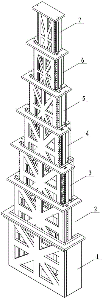
[0017] Embodiment 1: Combining Figure 1 to Figure 6 Illustrating this embodiment, this embodiment includes a boom telescopic mechanism, two hydraulic cylinders 21, six extension chains 19, six retraction chains 20, twelve single guide rails 11, twelve single guide rail guide wheels 12, twelve Extending sprocket 13, twelve inner jacking pulleys 14, twelve retracting sprockets 15, twelve outer jacking pulleys 16, twelve double guide rails 17 and twelve double guide rail guide pulleys 18, joint arm The telescopic mechanism includes seven telescopic sections. The seven telescopic sections from bottom to top are the first telescopic section 1, the second telescopic section 2, the third telescopic section 3, the fourth telescopic section 4, the fifth telescopic section 5, and the sixth telescopic section. Section 6 and the seventh telescopic section 7, each telescopic section consists of a box body 8, a box body top plate 9 and a box body bottom plate 10, the cross-sectional shape ...

specific Embodiment approach 2

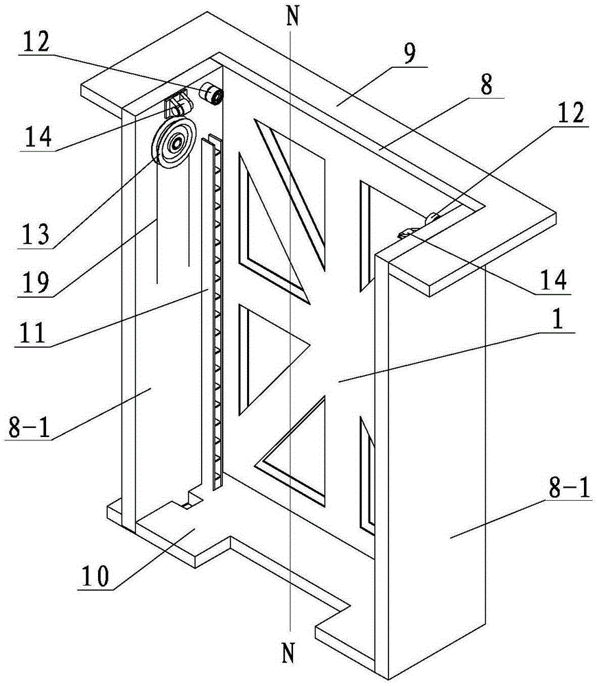
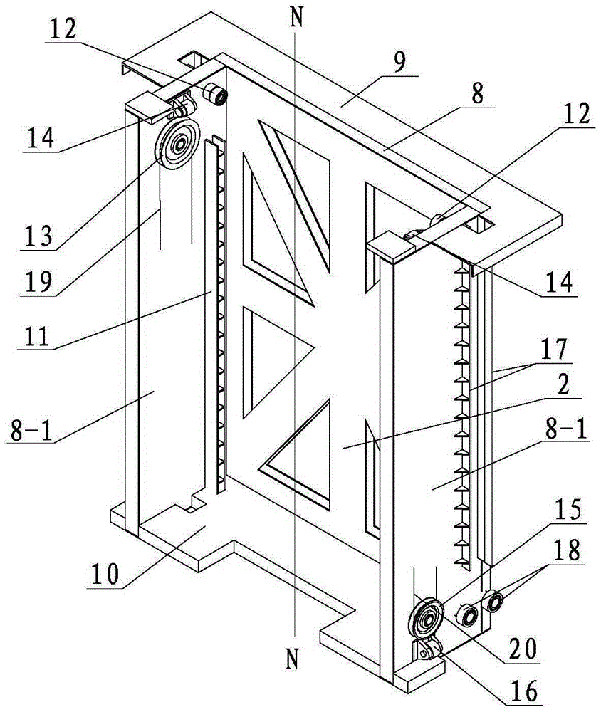
[0019] Specific implementation mode 2: Combining figure 2 and image 3 Illustrating this embodiment, the two single guide rails 11 on each box body 8 in this embodiment are symmetrically arranged on the vertical center line N-N of the box body 8 . This is designed to increase the smoothness of the transmission. Other components and connection relationships are the same as in the first embodiment.

specific Embodiment approach 3

[0020] Specific implementation three: combination figure 2 and image 3 Illustrating this embodiment, the two elongated sprockets 13 on each box body 8 in this embodiment are symmetrically arranged with respect to the vertical center line N-N of the box body 8 . This is designed to increase the smoothness of the transmission. Other components and connection relationships are the same as in the second embodiment.


PUM


Abstract

The invention discloses a telescopic radar antenna back frame, relates to a radar antenna auxiliary tool, and aims to solve the problem of large size, inconvenient transport and poor mobility of the existing radar antenna back frame. A first telescopic joint, a second telescopic joint, a third telescopic joint, a fourth telescopic joint, a fifth telescopic joint, a sixth telescopic joint, and a seventh telescopic joint are embedded in sequence from the bottom up; a single guide rail in each telescopic joint is formed in dual guide rails in a corresponding telescopic joint; every two extension chain wheels that are adjacent up and down are wrapped with an extension chain; every two retracting chain wheels that are adjacent up and down are wrapped with a retracting chain; two hydraulic cylinders are arranged symmetrically around a vertical central line of a box body; and one end of each hydraulic cylinder is hinged with the lower end plane of the bottom plate of the box body on the second telescopic joint while the other end of the hydraulic cylinder is hinged with the upper end plane of the bottom plate of the box body on the first telescopic joint. The telescopic radar antenna back frame is used for supporting the radar antenna.

Description

technical field [0001] The invention relates to a radar antenna auxiliary tool, in particular to a retractable radar antenna back frame. Background technique [0002] Radar detection technology plays a vital role in modern warfare characterized by long-range strikes and precision strikes, and is an important means to carry out functions such as military reconnaissance, strategic early warning, and target surveillance. Modern high-tech warfare has put forward higher and higher requirements for radar's cross-country combat and battlefield survivability, and high maneuverability has become an essential quality of modern military radar. The mobility of the radar is mainly reflected in the following aspects: the erection and withdrawal time of the entire radar, the off-road performance of transportation and the diversification of transportation methods. Loading all radar equipment in a heavy or neutral off-road vehicle without overrunning or overweight, this single-vehicle high-...

Claims


Application Information

Patent Timeline
Patent Type & Authority Applications(China)
IPC IPC(8): H01Q1/10
CPCH01Q1/10
Inventor 彭高亮薛渊刘世伟赵杰
Owner HARBIN INST OF TECH
Why Eureka
Try Eureka