Check patentability & draft patents in minutes with Patsnap Eureka AI!

An automatic clamping machine of a lamp cap

An automatic clamping and lamp cap technology, applied in workpiece clamping devices, manufacturing tools, etc., can solve the problems of large cylinder energy consumption, fast cylinder loss, and high cost, and achieve extended service life, reduced process costs, and reduced use frequency. Effect

Active Publication Date: 2017-06-23
JIANGXI TOP VISION TECH CO LTD
View PDF7 Cites 0 Cited by
  • Summary
  • Abstract
  • Description
  • Claims
  • Application Information

AI Technical Summary

Problems solved by technology

Therefore, the cylinder needs to work continuously during the whole operation, so the energy consumption of the cylinder is quite large, not only the cost of the process is very high, but also the loss of the cylinder is very fast, which seriously affects the entire service life of the clamping machine

Method used


Image

  • An automatic clamping machine of a lamp cap

Examples


Embodiment Construction

[0008] Below in conjunction with accompanying drawing and specific embodiment, further illustrate the present invention, should be understood that these embodiments are only for illustrating the present invention and are not intended to limit the scope of the present invention, after having read the present invention, those skilled in the art will understand various aspects of the present invention Modifications in equivalent forms all fall within the scope defined by the appended claims of this application.

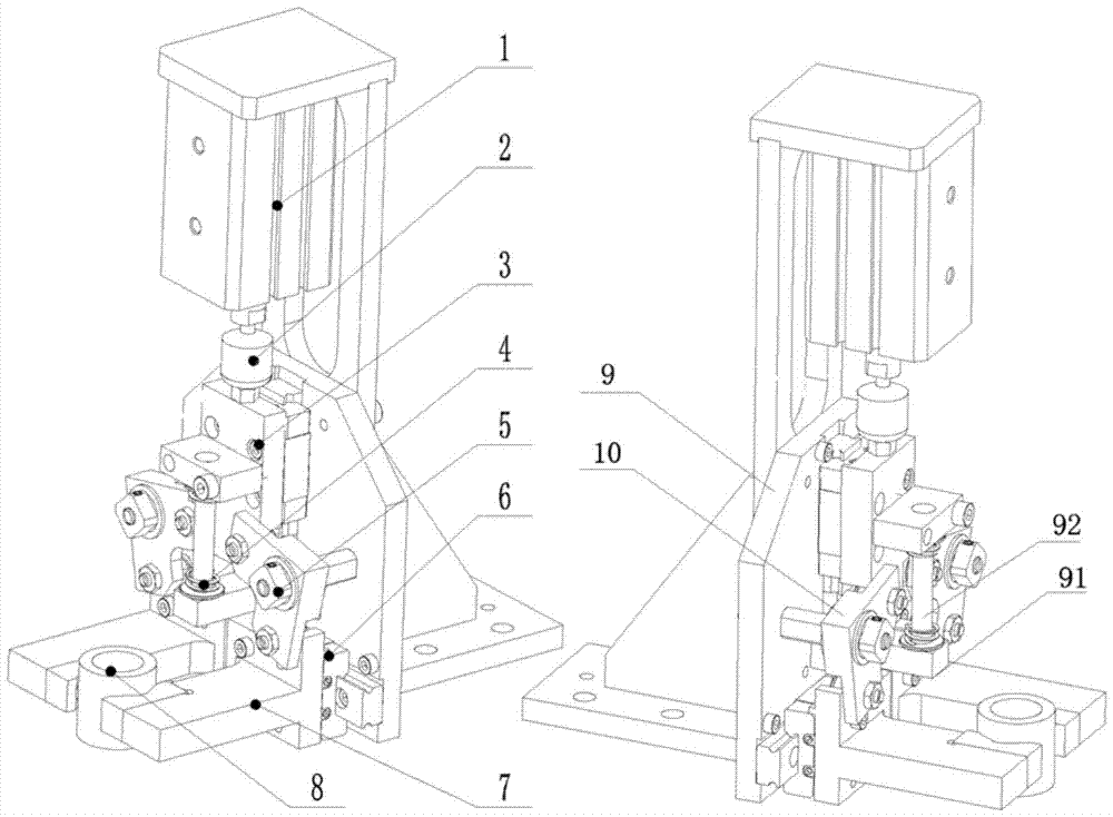
[0009] Such as figure 1 As shown, the present invention provides an automatic clamping machine for lamp caps, which includes a cylinder 1 and a bracket 9, and also includes a push head 2 connected to the lower end of the cylinder 1, a line rail slider 3 connected to the lower end of the push head 2, and the bracket 9. A horizontal support block 91 is arranged horizontally below the line rail slider 3, and a telescopic column 92 is longitudinally arranged on the horizonta...


PUM


Abstract

The invention discloses an automatic clamping machine for a lamp cap. The machine comprises a cylinder, a bracket, a pushing head which is connected to the lower end of the cylinder, and a line rail slide block which is connected to the lower end of the pushing head, wherein a transverse supporting block is transversely arranged at a part, below the line rail slide block, of the bracket; a telescoping column which passes through the line rail slide block is lengthways arranged on the transverse supporting block; a pre-tensioning spring coils the telescoping column; fixing shafts are transversely arranged at two ends of the bracket. Compared with the prior art, the machine has the advantages that the lamp cap can be tightened without the effect of the cylinder, so that the use frequency of the cylinder in the whole process can be greatly reduced, and as a result, the process cost can be reduced, and moreover, the service life of the cylinder rand even the whole automatic clamping machine can be further prolonged.

Description

technical field [0001] The invention specifically relates to an automatic lamp cap clamping machine. Background technique [0002] The process of tightening and loosening the lamp cap by the existing lamp cap automatic clamping machine requires the operation of the cylinder to complete the corresponding operation. Therefore, the cylinder needs to work continuously during the whole operation, so the energy consumption of the cylinder is quite large, not only the cost of the process is very high, but also the loss of the cylinder is very fast, which seriously affects the entire service life of the clamping machine. Contents of the invention [0003] Purpose of the invention: In order to overcome the deficiencies in the prior art, provide an automatic lamp cap clamping machine that can achieve the purpose of tightening without the need for energy provided by the cylinder during the clamping operation of the lamp cap. [0004] Technical solution: In order to achieve the above...

Claims


Application Information

Patent Timeline
Patent Type & Authority Patents(China)
IPC IPC(8): B25B11/00
CPCB25B11/00
Inventor 徐文波沈立
Owner JIANGXI TOP VISION TECH CO LTD
Features
  • R&D
  • Intellectual Property
  • Life Sciences
  • Materials
  • Tech Scout
  • Unparalleled Data Quality
  • Higher Quality Content
  • 60% Fewer Hallucinations
Learn More