Substrate transporting device and substrate transporting method

A substrate conveying and conveying direction technology, applied in the direction of conveyor objects, transportation and packaging, rollers, etc., can solve the problems of guide roller wear and other problems, and achieve the effect of extending life

Active Publication Date: 2016-03-23
SHIBAURA MECHATRONICS CORP
View PDF7 Cites 9 Cited by
  • Summary
  • Abstract
  • Description
  • Claims
  • Application Information

AI Technical Summary

Problems solved by technology

In particular, if the thickness of the substrate becomes thinner, the side surface of the substrate acts on the guide roller like a knife edge, and the guide roller wears rapidly, therefore, it is necessary to frequently replace the guide roller in a short period of time

Method used


Image

  • Substrate transporting device and substrate transporting method
  • Substrate transporting device and substrate transporting method
  • Substrate transporting device and substrate transporting method

Examples


no. 1 Embodiment approach

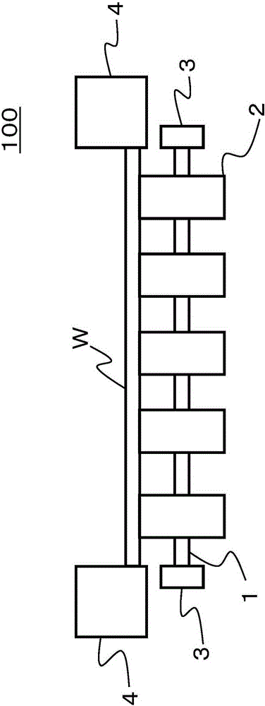
[0018] refer to Figure 1 to Figure 4 The first embodiment will be described.

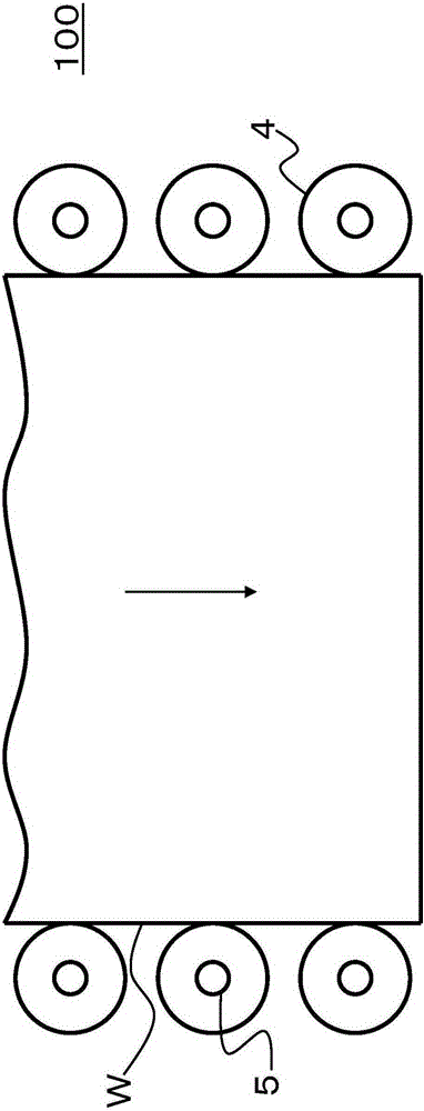
[0019] Such as figure 1 , figure 2 As shown, the substrate transfer apparatus 100 of the first embodiment has a shaft 1 provided along the transfer direction of the substrate W (in figure 1 The direction perpendicular to the paper surface) (hereinafter, also referred to as "the width direction of the substrate W") extends; the conveying roller 2, which is provided on the shaft 1 in a plurality at regular intervals, and is arranged as abuts against the lower surface of the base plate W; and a bearing 3 that holds the shaft 1 . Furthermore, a plurality of guide rollers 4 pass through shafts 5 (see figure 2 ) to set. The guide roller 4 is made of an elastic body such as rubber or resin, and is formed in a cylindrical shape having a height twice or more than the thickness of the substrate W. image 3 , Figure 4 As explained above, each guide roller 4 is configured to be capable of adjusting t...

no. 2 Embodiment approach

[0040] refer to Figure 5 , Image 6 A second embodiment will be described.

[0041] The second embodiment is basically the same as the first embodiment. Therefore, in the second embodiment, differences from the first embodiment will be described, and the same parts as those described in the first embodiment will be denoted by the same reference numerals, and descriptions thereof will be omitted.

[0042] Such as Figure 5 As shown, the substrate conveying apparatus according to the second embodiment includes a guide roller adjustment unit 400 . The X-axis adjustment mechanism of the guide roller adjustment unit 400 is the same as the X-axis adjustment mechanism 200 of the first embodiment. Unlike the first embodiment, the Z-axis adjustment mechanism includes an adjustment member (spacer member) 400A between the fixed member 41 and the second movable member 42 . The position of the guide roller 4 in the Z direction can be adjusted by preparing a plurality of adjusting mem...


PUM


Abstract

The invention provides a substrate transporting device and a substrate transporting method, wherein the service life of guide rollers is prolonged. Meanwhile, substrates are conveyed straightly along the linear direction. The substrate transporting device is characterized by comprising a plurality of transport rollers (2) that abut against the lower surface of a substrate and used for transporting the substrate along a predetermined direction; a plurality of guide rollers (4) arranged along the substrate transporting direction and used for clamping the substrate along a direction vertical to the transporting direction; and a guide roller adjustment part (40) used for adjusting the positions of the guide rollers. The guide roller adjustment part (40) is composed of a first movable component (45) for keeping the guide rollers (4) to rotate, and a Z-axis adjustment mechanism (300) for adjusting the height position of the first movable component (45) in the thickness direction of the substrate (W).

Description

technical field [0001] Embodiments of the present invention relate to a substrate transfer device and a substrate transfer method. Background technique [0002] As a substrate conveying device, a device is known in which a plurality of conveying rollers are provided on a shaft extending perpendicularly to the conveying direction of the substrate, and the substrate is conveyed by contacting the lower surface of the substrate to the conveying rollers. Furthermore, this substrate conveying device is configured such that, in addition to the conveying rollers, a plurality of guide rollers are provided along the conveying direction of the substrate to be conveyed, and the side surfaces of the substrate are guided by the guide rollers, thereby conveying the substrate to the conveyed rollers. The substrate is positioned, and the substrate can be transported without meandering. [0003] Patent Document 1: Japanese Unexamined Patent Publication No. 2010-42902 [0004] The substrate ...

Claims


Application Information

Patent Timeline
IPC IPC(8): B65G13/00B65G39/18H01L21/677
Inventor 标克彦矶明典高原龙平
Owner SHIBAURA MECHATRONICS CORP
Why Eureka
Try Eureka