Conveying device

A conveying device and conveying belt technology, applied in conveyors, vibrating conveyors, transportation and packaging, etc., can solve the problems of high cost, low efficiency, unsuitable manual handling, etc., achieve low cost, improve conveying efficiency, and simple structure Effect

Inactive Publication Date: 2016-03-23
WUXI ZHENGYANG MACHINERY
View PDF6 Cites 8 Cited by
  • Summary
  • Abstract
  • Description
  • Claims
  • Application Information

AI Technical Summary

Problems solved by technology

[0002] Wood processing is common in industrial production. Wood can be made into pallets, beams, etc. after processing. There are generally many processes in the processing of wood. In the middle of the processing process, wood needs to be transported. Manual handling is no longer suitable, and it is now common. They are all conveyed by conveyor belts or conveying rollers. During the conveying p

Method used


Image

  • Conveying device
  • Conveying device
  • Conveying device

Examples


Embodiment Construction

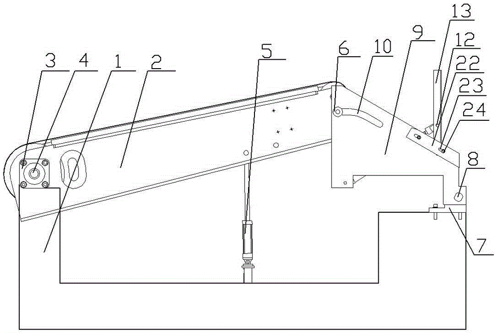
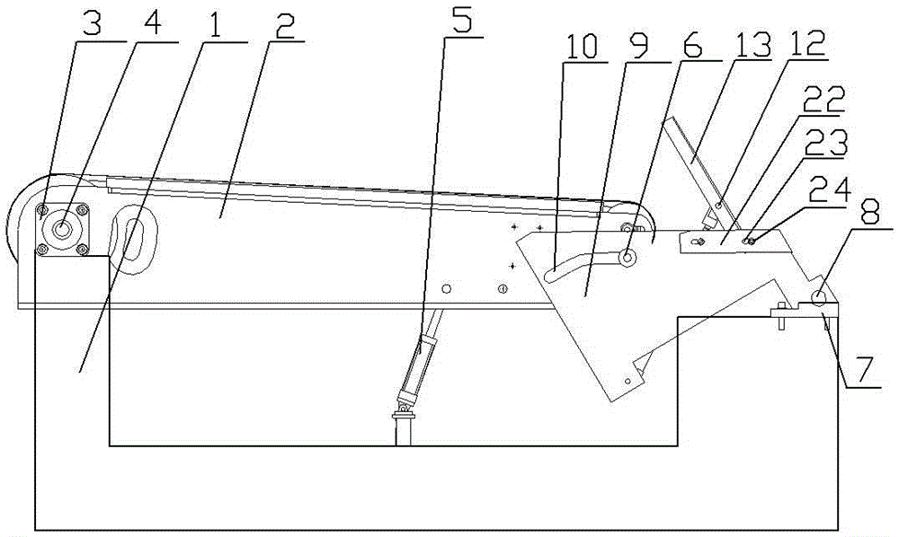
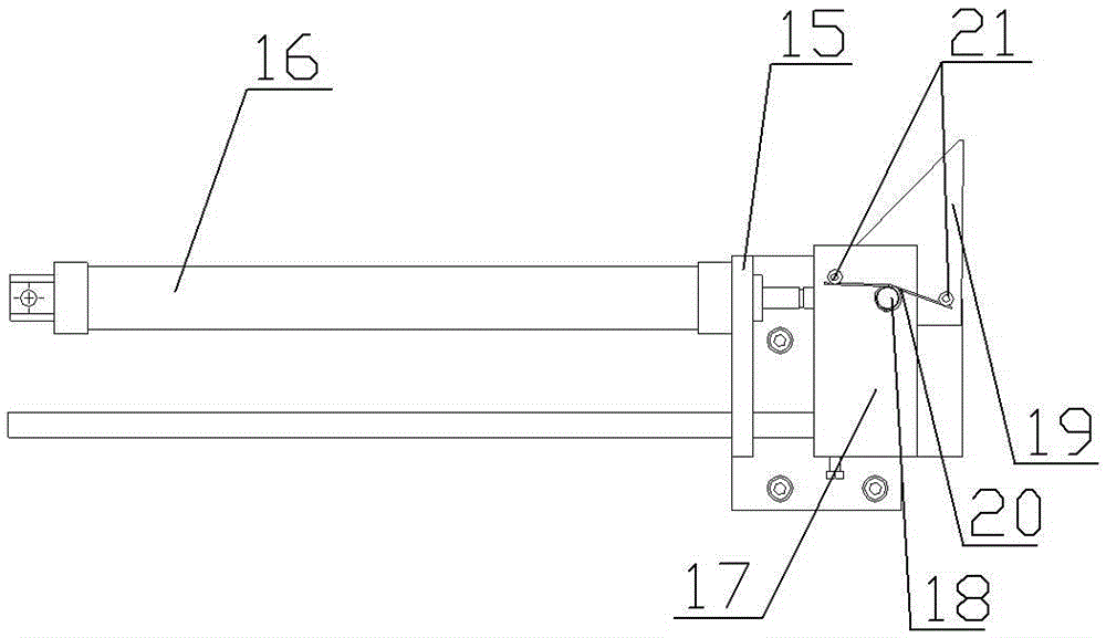
[0012] See figure 1 , figure 2 , image 3 , Figure 4 As shown, a conveying device includes a base 1 and a conveyor belt 2. A bearing seat 3 is installed on one end of the base 1, and a slanting device is installed on the other end. The driving wheel of the conveyor belt 2 is connected to the bearing seat 3 through a drive shaft 4. The drive shaft 4 is connected to the drive motor (not shown in the figure), the lower end of the conveyor belt 2 is hinged to the piston rod of the lifting cylinder 5, the cylinder body of the lifting cylinder 5 is hinged to the base 1, and the shaft side of the driven wheel of the conveyor belt 2 is equipped with a slide bar 6. The inclined sliding device includes an inclined sliding plate fixing seat 7 fixedly installed on the base 1. The inclined sliding plate fixing seat 7 is connected to the inclined sliding plate 9 through the first pin shaft 8. The inclined sliding plate 9 is provided with a slope, and the inclined sliding plate 9 is prov...


PUM


Abstract

The invention relates to the technical field of timber conveying, in particular to a conveying device. Vertical conveying and horizontal conveying of timber can be conveniently achieved, the conveying efficiency is improved, and the cost is low. The conveying device comprises a base and a conveying belt; a bearing pedestal is installed at one end of the base; an inclined sliding device is installed at the other end of the base; a drive wheel of the conveying belt is connected with the bearing pedestal through a drive shaft; the drive shaft is connected with a drive motor; the lower end of the conveying belt is hinged to a piston rod of a lifting air cylinder; a cylinder body of the lifting air cylinder is hinged to the base; the shaft side portion of a driven wheel of the conveying belt is provided with a sliding rod; the inclined sliding device comprises an inclined sliding board fixed base fixedly installed on the base; the inclined sliding board fixed base is connected with an inclined sliding board through a first pin shaft; the inclined sliding board is provided with a slope; a sliding groove is formed in the inclined sliding board; the sliding rod is arranged in the sliding groove; an overturning cylinder is installed on one side of the inclined sliding board; a cylinder of the overturning cylinder is hinged to the inclined sliding board; a piston rod of the overturning cylinder is connected with the middle of an inclined pushing rod through a second pin shaft; the lower end of the inclined pushing rod is connected with the inclined sliding board through a third pin shaft.

Description

technical field [0001] The invention relates to the technical field of wood conveying, in particular to a conveying device. Background technique [0002] Wood processing is common in industrial production. Wood can be made into pallets, beams, etc. after processing. There are generally many processes in the processing of wood. In the middle of the processing process, wood needs to be transported. Manual handling is no longer suitable, and it is now common. They are all conveyed by conveyor belts or conveying rollers. During the conveying process, there are two conveying methods: vertical conveying and horizontal conveying of wood. For different kinds of wood, it is sometimes necessary to use the two conveying methods according to actual needs. Flip adjustment, the existing common practice is to manually flip it manually, the efficiency is low, and if the flip operation is performed by a mechanical arm, the cost is relatively high. Contents of the invention [0003] In ord...

Claims


Application Information

Patent Timeline
IPC IPC(8): B65G27/08
CPCB65G27/08
Inventor 谢新华
Owner WUXI ZHENGYANG MACHINERY
Why Eureka
Try Eureka