Hydraulic system, motor sweeper hydraulic system and motor sweeper with motor sweeper hydraulic system

A technology of hydraulic system and hydraulic oil, applied in the field of sweepers, can solve the problem of high cost and achieve the effect of reducing equipment cost, reducing requirements and saving size

Inactive Publication Date: 2016-03-23
CHANGSHA FOTON AUTOMOBILE TECH
View PDF7 Cites 6 Cited by
  • Summary
  • Abstract
  • Description
  • Claims
  • Application Information

AI Technical Summary

Problems solved by technology

[0005] Therefore, the technical problem to be solved by the present invention is to overcome the need to increase the volume of the hydraulic oil tank and adopt a gear pump with a larger displacement in order to ensure the supply of hydraulic oil after the hydraulic system in the prior art increases the components to be driven, so that the cost is too high Therefore, even after increasing the number of components to be driven, without increasing the volume of the hydraulic oil tank and without using a gear pump with a larger displacement, the supply of hydraulic oil can be guaranteed, so the cost of hydraulic pressure is lower. system

Method used


Image

  • Hydraulic system, motor sweeper hydraulic system and motor sweeper with motor sweeper hydraulic system
  • Hydraulic system, motor sweeper hydraulic system and motor sweeper with motor sweeper hydraulic system
  • Hydraulic system, motor sweeper hydraulic system and motor sweeper with motor sweeper hydraulic system

Examples


Embodiment 1

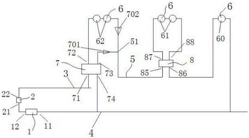
[0053] This embodiment provides a specific implementation of a hydraulic system, such as figure 1 As shown, the hydraulic system includes:

[0054] Hydraulic oil tank 1, used to store hydraulic oil, has a hydraulic oil inlet 11 and a hydraulic oil outlet 12;

[0055] The hydraulic pump 2 has a hydraulic pump inlet 21 and a hydraulic pump outlet 22, and the hydraulic pump inlet 21 communicates with the hydraulic oil outlet 12 through a pipeline;

[0056] The oil delivery pipe 3 communicates with the hydraulic pump outlet 22 and is used to supply the hydraulic oil in the hydraulic oil tank 1 to the hydraulic motor 6;

[0057] The oil return pipe 4 communicates with the hydraulic oil inlet 11 and is used to recover the hydraulic oil in the pipeline to the hydraulic oil tank 1;

[0058] There is at least one oil pipe 5, and its two ends communicate with the oil outlet of the oil delivery pipe 3 and the oil inlet of the oil return pipe 4 respectively;

[0059] There are multiple...

Embodiment 2

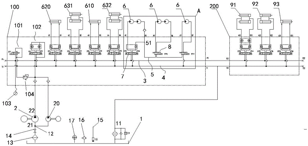
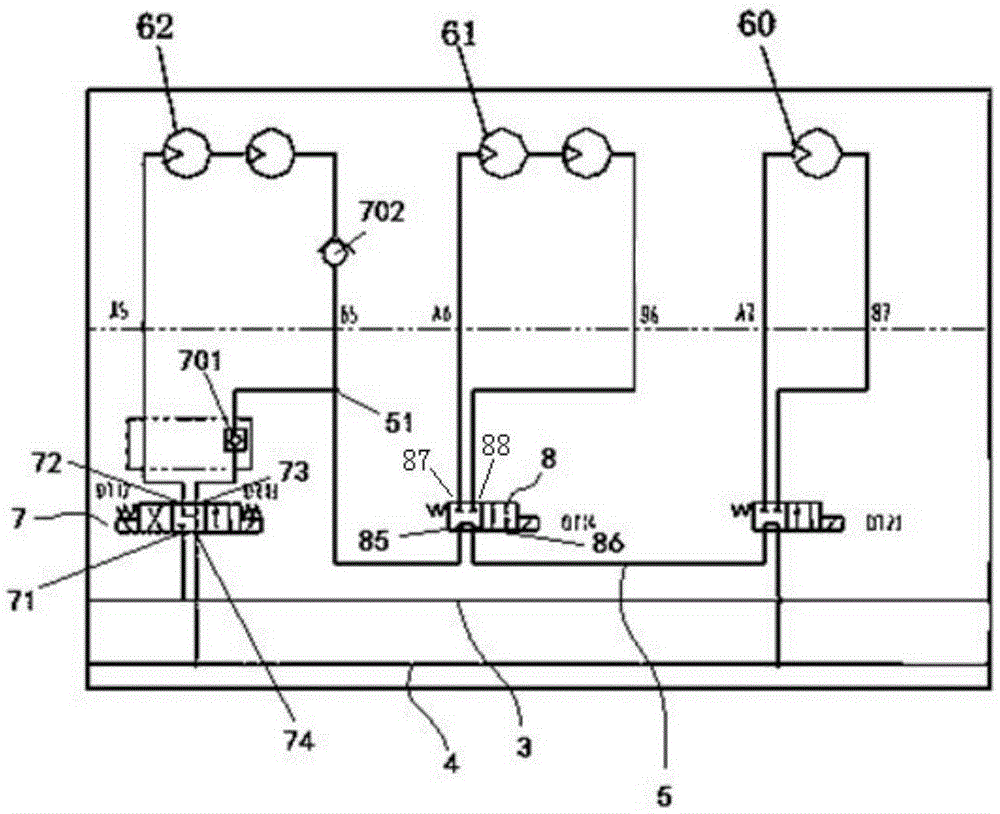
[0078] This embodiment provides a sweeping vehicle hydraulic system, which is a specific application of the hydraulic system provided in Embodiment 1, such as figure 2 and image 3 As shown, the sweeper hydraulic system includes:

[0079] Hydraulic oil tank 1, used to store hydraulic oil, has a hydraulic oil inlet 11 and a hydraulic oil outlet 12;

[0080] The hydraulic pump 2 has a hydraulic pump inlet 21 and a hydraulic pump outlet 22, and the hydraulic pump inlet 21 communicates with the hydraulic oil outlet 12 through a pipeline;

[0081] The oil delivery pipe 3 communicates with the hydraulic pump outlet 22 and is used to supply the hydraulic oil in the hydraulic oil tank 1 to the hydraulic motor 6;

[0082] The oil return pipe 4 communicates with the hydraulic oil inlet 11 and is used to recover the hydraulic oil in the pipeline to the hydraulic oil tank 1;

[0083] An oil pipe 5 is one, and its two ends communicate with the oil outlet of the oil delivery pipe 3 and th...

Embodiment 3

[0096] This embodiment provides a sweeping vehicle, which includes a hydraulic system, two left sweeping discs located on the left side of the sweeping vehicle along the traveling direction of the sweeping vehicle, two right sweeping discs located on the right side of the sweeping vehicle, and A rolling sweep at the bottom. Wherein, the hydraulic system is the hydraulic system of any one of the implementations described in Example 1 or Example 2.

[0097] Owing to having the above hydraulic system, it has the advantages described in any one of the above.


PUM


Abstract

The invention provides a hydraulic system, a motor sweeper hydraulic system and a motor sweeper with the motor sweeper hydraulic system. The hydraulic system comprises a hydraulic oil tank, a hydraulic pump, an oil conveying pipe, an oil return pipe, at least one oil pipe and a plurality of hydraulic motors. The hydraulic oil tank is provided with a hydraulic oil inlet and a hydraulic oil outlet. The hydraulic pump is provided with a hydraulic pump inlet and a hydraulic pump outlet, and the hydraulic pump inlet is communicated with the hydraulic oil outlet through a pipe. The oil conveying pipe is communicated with the hydraulic pump outlet. The oil return pipe is communicated with the hydraulic oil inlet. The two ends of the oil pipes are communicated with the oil conveying pipe and the oil return pipe respectively. At least two hydraulic motors are connected to one oil pipe in series. Compared with a hydraulic system in the prior art, according to the hydraulic system, the number of branches from the oil conveying pipe to the oil return pipe is lowered, the requirements for the hydraulic oil tank and a gear pump are lowered, and equipment cost is greatly reduced.

Description

technical field [0001] The invention relates to the technical field of hydraulic systems, in particular to a hydraulic system, a cleaning vehicle hydraulic system and a cleaning vehicle equipped with the hydraulic system. Background technique [0002] Sweeping vehicles are mainly used for road rubbish cleaning on urban roads, and generally include multiple side sweeping discs driven by hydraulic motors, and suction cups connected to fans. When the hydraulic motor drives the side sweeping disc to work, the side sweeping disc sweeps the garbage to the vicinity of the suction cup, and the fan rotates to make the suction cup generate negative pressure to suck out the garbage. When the road conditions are poor or there is too much rubbish on the road surface, it is necessary to add a rolling sweeper to continue sweeping the rubbish that has not been sucked up by the suction cup until the sucker completely sucks all the rubbish away. [0003] In the hydraulic system of the cleani...

Claims


Application Information

Patent Timeline
Patent Type & Authority Applications(China)
IPC IPC(8): F15B11/16F15B21/04E01H1/05
Inventor 徐清平陈志李妮娜
Owner CHANGSHA FOTON AUTOMOBILE TECH
Why Eureka
Try Eureka