
Pilot high-pressure valve

A technology of pilot valve and high-pressure valve, applied in the field of high-pressure valve, can solve the problems of long switching time, poor stability, low quality of plastic bottles, etc., and achieve the effect of long service life and high integrity

Active Publication Date: 2016-03-23
GUTANG MEASUREMENT & CONTROL TECH SHANGHAI CO LTD
View PDF6 Cites 0 Cited by
  • Summary
  • Abstract
  • Description
  • Claims
  • Application Information

AI Technical Summary

Problems solved by technology

Due to the long switching time and poor stability of the diaphragm high-pressure valve, the bottle blowing speed is slow and the quality of the processed plastic bottles is low
In addition, the life of the diaphragm in this diaphragm high-pressure valve is not very long, so it can only be used in some low-end blow molding machines

Method used


Image

  • Pilot high-pressure valve
  • Pilot high-pressure valve
  • Pilot high-pressure valve

Examples


Embodiment 1

[0068] Example 1, such as figure 1 , figure 2 with Figure 5 as shown,

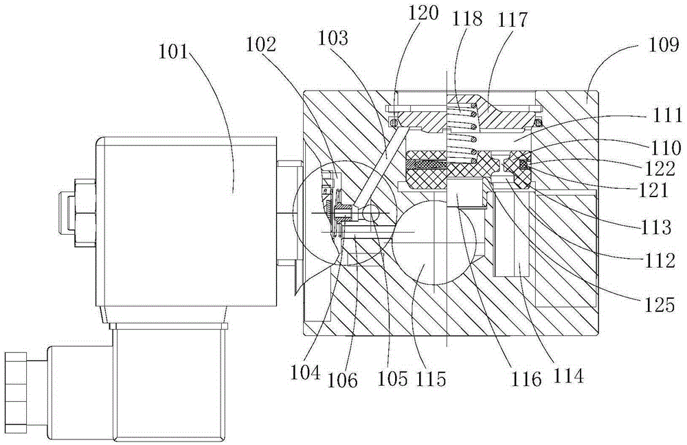
[0069] A pilot-operated high-pressure valve, including a pilot valve 101 and a main valve, the main valve includes a cylinder 109, a piston 110, a main valve inlet 114 and a main valve outlet 115, and the piston 110 transfers the air in the cylinder 109 The space is divided into an upper chamber 111 and a lower chamber 112, a through hole 113 is provided between the upper chamber 111 and the lower chamber 112, the lower chamber 112 communicates with the main valve air inlet 114, and the main valve The air outlet 115 is arranged on the lower end surface of the piston 110;

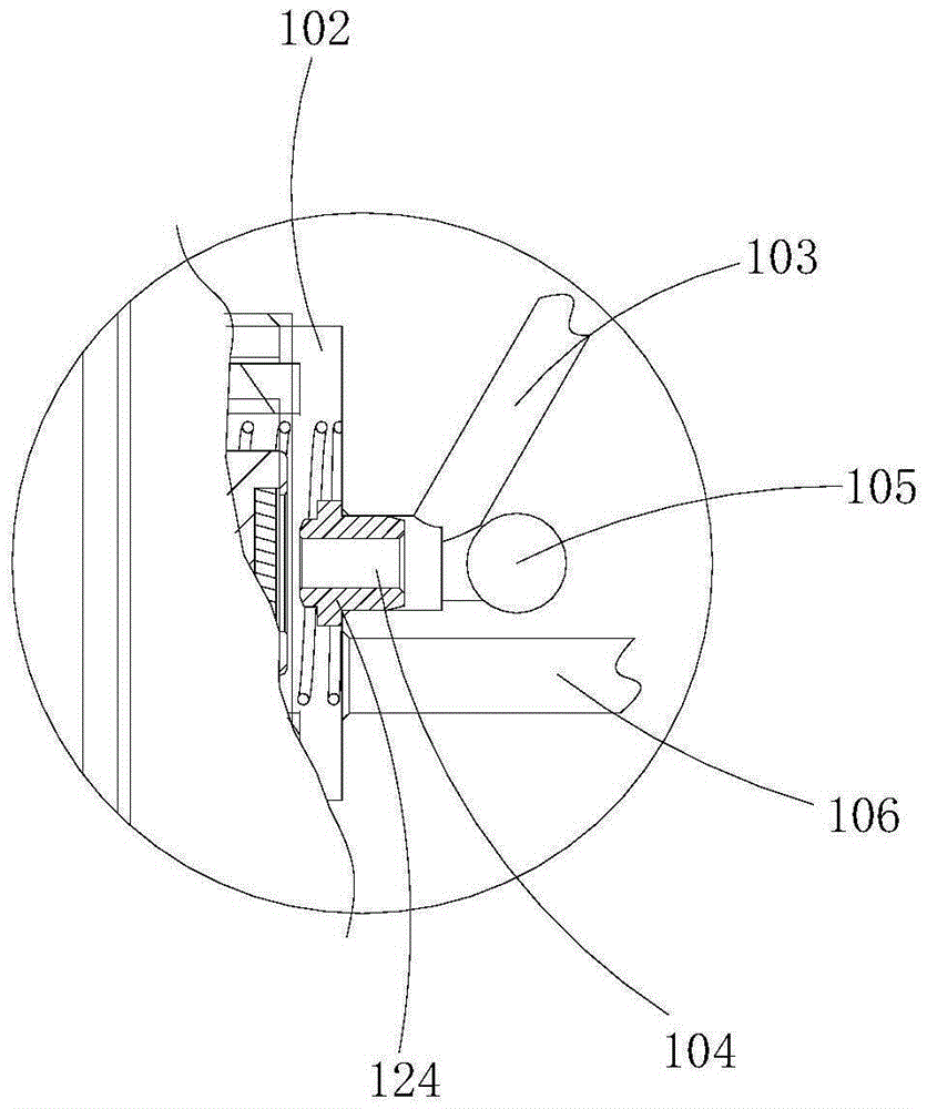
[0070] The pilot valve 101 is provided with a pilot valve chamber 102 and a spool 1012, the pilot valve chamber 102 is provided with a pilot valve port 104 at a position corresponding to the spool 1012, and the pilot valve 101 is provided with The pilot valve inlet 103 and the pilot valve channel 105, the pilot valve channel 105 co...

Embodiment 2

[0072] Example 2, such as image 3 with Figure 4 as shown,

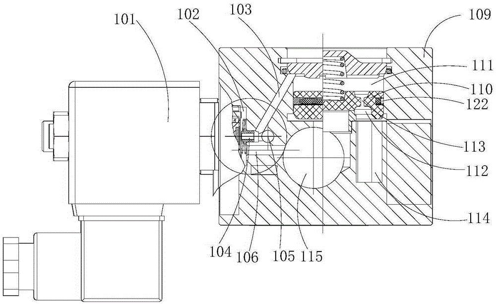
[0073] A pilot-operated high-pressure valve, including a pilot valve 101 and a main valve, the main valve includes a cylinder 109, a piston 110, a main valve inlet 114 and a main valve outlet 115, and the piston 110 transfers the air in the cylinder 109 The space is divided into an upper chamber 111 and a lower chamber 112, a through hole 113 is provided between the upper chamber 111 and the lower chamber 112, the lower chamber 112 communicates with the main valve air inlet 114, and the main valve The air outlet 115 is arranged on the lower end surface of the piston 110;

[0074] The pilot valve 101 is provided with a pilot valve chamber 102 and a spool 1012, the pilot valve chamber 102 is provided with a pilot valve port 104 at a position corresponding to the spool 1012, and the pilot valve 101 is provided with The pilot valve inlet 103 and the pilot valve channel 105, the pilot valve channel 105 communicates wi...


PUM


Abstract

The invention provides a pilot high-pressure valve, and belongs to the field of high-pressure valves. The pilot high-pressure valve comprises a pilot valve and a main valve; the main valve includes a cylinder, a piston, a main valve intake port and a main valve exhaust port; a space in the cylinder is divided into an upper cavity and a lower cavity by the piston; a through hole is formed between the upper cavity and the lower cavity; the lower cavity is communicated with the main valve intake port; the main valve exhaust port is formed in the lower end surface of the piston; a pilot valve cavity and a valve element are arranged in the pilot valve; a pilot valve port is formed in the pilot valve cavity opposite to the valve element; the pilot valve is provided with a pilot valve intake port and a pilot valve channel; the pilot valve channel is communicated with the pilot valve port; and the pilot valve intake port is communicated with the upper cavity of the main valve. The pilot high-pressure valve is compact in structure, short in opening / closing time, high in stability and long in service life.

Description

technical field [0001] The invention relates to the field of high-pressure valves, in particular to a pilot-operated high-pressure valve. Background technique [0002] High-pressure valves have been widely used in various fields of industrial manufacturing, mainly used to control the flow of various types of fluids such as gas and liquid. At present, the high-pressure air supply valve used in the equipment for the production of plastic bottles is a solenoid valve with an internal pilot diaphragm structure, referred to as a diaphragm high-pressure valve for short. The inner pilot diaphragm high-pressure valve is a two-position two-way valve. Blow molding machine manufacturers usually need to integrate multiple such valves according to the requirements of the blow molding process to complete several key steps in the blow molding process: medium and high pressure pre-blowing preforms; high-pressure blowing to shape the plastic bottle; high-pressure gas discharge . Due to the...

Claims


Application Information

Patent Timeline
IPC IPC(8): F16K1/00F16K31/40F16K31/06
CPCF16K1/00F16K31/0655F16K31/406
Inventor 辜庆华
Owner GUTANG MEASUREMENT & CONTROL TECH SHANGHAI CO LTD
Learn More