
Circuit breaker and solid-sealed pole thereof

A technology for solid-sealing poles and assembly holes, which is applied to high-voltage air circuit breakers, circuits, electrical components, etc., can solve the problems of contact surface wear, affecting the current conductivity performance of solid-sealing poles, and reducing the reliability of conductive contacts.

Active Publication Date: 2016-03-23
TIANJIN PINGGAO INTELLIGENT ELECTRIC +2
View PDF6 Cites 8 Cited by
  • Summary
  • Abstract
  • Description
  • Claims
  • Application Information

AI Technical Summary

Problems solved by technology

However, the surface contact and cooperation between the contact fingers of the watch strap and the conductive sleeve will also increase the required operating force for the opening and closing operation of the vacuum interrupter, which will increase the load on the operating mechanism. During the closing process, the friction between the conductive sleeve and the contact fingers of the watch strap will cause the contact surface of the two to wear, which will reduce the reliability of the conductive contact between the conductive sleeve and the contact fingers of the strap, and increase the heat generated by the conduction. , affecting the conduction performance between the lower outgoing line of the solid-sealed pole and the vacuum interrupter

Method used


Image

  • Circuit breaker and solid-sealed pole thereof
  • Circuit breaker and solid-sealed pole thereof

Examples


Embodiment Construction

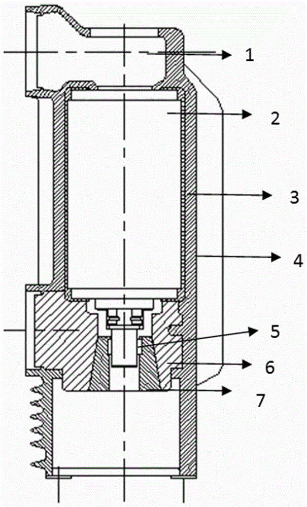
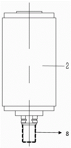
[0020] The embodiment of circuit breaker in the present invention: as figure 1 and figure 2 As shown, the circuit breaker is a DC vacuum circuit breaker, including the operating mechanism and several solid-sealed poles connected by transmission on the output end. Connect the upper outgoing line 1, the vacuum interrupter 2, and the lower outgoing line 6. The lower end of the vacuum interrupter 2 is provided with a vertically extending movable end conductive rod 8, and the movable end conductive rod 8 moves along the up and down direction and is mounted on the lower outgoing line 6. In the upper and lower extension assembly holes opened, the bottom of the hole wall of the assembly hole is a tapered hole section that gradually increases from top to bottom, and the conductive hole sleeved on the outer circumference of the movable end conductive rod 8 is fixed in the tapered hole section through the cooperation of the tapered surface. Sleeve 7, the inner hole of the conductive sl...


PUM


Abstract

The present invention discloses a circuit breaker and a solid-sealed pole thereof. The solid-sealed pole comprises an upper outgoing line, an arc extinguish chamber, and a lower outgoing line which are sequentially and electrically connected from top to bottom. The lower outgoing line is provided with a fitting hole extending up and down; the lower end of the arc extinguish chamber is provided with a running end conductive rod which is piloted to move in an up-and-down direction to be worn in the fitting hole; an annular contact finger is arranged at an interval between the peripheral surface of the running end conductive rod and the hole wall surface of the fitting hole; the contact finger is fixed on one of the peripheral surface of the running end conductive rod and the hole wall surface of the fitting hole; a graphite layer is arranged at an interval between the other one of the peripheral surface of the running end conductive rod and the hole wall surface of the fitting hole and the strap touch finger; and the graphite layer is on the touch finger or is in pilot moving fit with the touch finger in the up-and-down direction. By self-lubricating performance of the graphite layer, when the graphite layer is on the touch finger, the friction between the graphite layer and the peripheral surface of the running end conductive rod or the hole wall surface of the fitting hole, which is in contact with the graphite layer, is reduced; and when the graphite layer is in sliding fit with the touch finger, the friction between the graphite layer and the touch finger is reduced so as to reduce the friction between the runing end conductive rod and the fitting hole.

Description

technical field [0001] The invention relates to a circuit breaker and its solid-sealed pole. Background technique [0002] At present, in medium and low voltage circuit breakers, in order to facilitate installation and maintenance, the vacuum interrupter is directly installed in the circuit breaker in the form of a solid-sealed pole. During the breaking process, the moving end connection of the vacuum interrupter is mainly used There are two ways, one is to use soft connection, but the design of soft connection is very complicated. In the case of solid sealing, due to the narrow space and hidden position, it cannot be assembled; the other way is to use spring contact fingers to connect. The line contact is connected with the moving end. When the moving end slides, the friction force is very large, and it will be severely worn after a period of time, resulting in rough surface of the conductive rod at the moving end and increased mechanism force. In DC circuit breakers, the q...

Claims


Application Information

Patent Timeline
IPC IPC(8): H01H33/66
CPCH01H33/66
Inventor 张雪敏王晓琴李文艺关琦李小钊侯小默李二肖
Owner TIANJIN PINGGAO INTELLIGENT ELECTRIC
Learn More