Conductive terminal

A technology of conductive wiring and terminals, which is applied in the direction of clamping/spring connection, etc., can solve the problems of unlocking failure, weakening of terminal spring elastic force, and high difficulty of assembly, and achieve the effects of avoiding free rotation, improving reliability, and high accuracy

Active Publication Date: 2016-03-23
CHINA AVIATION OPTICAL-ELECTRICAL TECH CO LTD
View PDF5 Cites 16 Cited by
  • Summary
  • Abstract
  • Description
  • Claims
  • Application Information

AI Technical Summary

Problems solved by technology

[0004] From the above simple description, it can be seen that the internal structure of the electrical connection terminal of the present invention is very complicated, the structure of the terminal spring, the operating element and the conductive metal parts inside the housing are all relatively complicated, the assembly difficulty is high, and the manufacturing cost is also high; the terminal When the spring rotates from the first position to the second position, it is driven by the pressure of the operating handle. When the terminal spring rotates from the second position to the first position, it is realized by the self-elasticity of the terminal spring, which leads to the unlocking of the wire is very difficult. Reliable, especially after a long time of use, the elastic force of the terminal spring is weakened, which can easily cause unlocking failure, low reliability, and very inconvenient to use

Method used


Image

  • Conductive terminal
  • Conductive terminal
  • Conductive terminal

Examples


Embodiment Construction

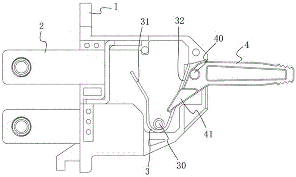
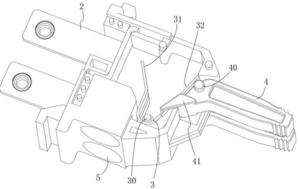
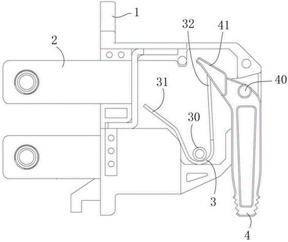
[0017] Embodiment 1 of the conductive terminal of the present invention: as Figure 1-4 As shown, a housing 1 is included, and the housing 1 is rotatably equipped with a crimping reed 3 around a rotating shaft 30 extending forward and backward. The casing 1 is also rotatably equipped with an operating handle 4 for driving the thread pressing reed 3 to rotate, and the rotation axes of the operating handle 4 and the thread pressing reed 3 are parallel. The casing 1 is provided with a threading hole 5 extending up and down and penetrating the inside and outside of the casing 1 , and the left side of the casing 1 is also provided with a conductive sheet 2 extending left and right. In this embodiment, there are two threading holes 5. Correspondingly, there are two conductive sheets 2. There are also two crimping reeds and operating handles respectively and arranged side by side. The threading holes, conductive sheet crimping reeds and The operating handles are in one-to-one corres...


PUM


Abstract

The present invention provides a conductive terminal. The terminal comprises a housing; a wire pressure reed is arranged in the housing in a manner of rotating around an axis extending front and back; the wire pressure reed is respectively provided with a wire pressure-wire end and a drive end on both sides of a rotating shaft; the housing is rotatably provided with an operating handle used for driving the wire pressure reed to rotate between a wire connection position and a wire pressure position; the operating handle is in parallel to the rotating axis of the wire pressure reed; one end of the operating handle, which is positioned inside the housing, is provided with a contact section; the contact section is provided with a reed perforated hole used for the drive end of the wire pressure reed to pass through; the reed perforated hole is provided with a right hole wall used for pushing the outer lateral surface of the drive end and enabling the wire pressure reed to rotate towards the wire pressure position when the operating handle rotates forwards; and the reed perforated hole is also provided with a left hole wall used for pulling the inner lateral surface of the drive end and enabling the wire pressure reed to rotate towards the wire connection position when the operating handle is rotated reversely. The conductive terminal disclosed by the present invention is simple in structure and very convenient to use.

Description

technical field [0001] The invention relates to a conductive connection device, in particular to a conductive connection terminal. Background technique [0002] Traditional electrical connection terminals are usually used to connect wires by means of screw crimping, which has problems such as complex structure, large size of connector, and inconvenient operation. In this regard, the Chinese invention patent with the authorized announcement number CN102204015B and the authorized announcement date of 2014.11.12 discloses an electrical connection terminal. There is a terminal spring inside, which is the crimping reed. The terminal spring can be deflected and placed in the housing so that it can go from the first position, that is, the wiring position, to the second position, that is, the crimping position. The terminal springs are respectively provided on both sides of the rotation axis. The terminal arm is the crimping end and the operating arm is the driving end. When the te...

Claims


Application Information

Patent Timeline
Patent Type & Authority Applications(China)
IPC IPC(8): H01R4/48
CPCH01R4/48
Inventor 李永聪周涛
Owner CHINA AVIATION OPTICAL-ELECTRICAL TECH CO LTD
Why Eureka
Try Eureka