Laser device for laser marking machine

A laser marking machine and laser device technology, applied in typewriters, laser parts, printing, etc., can solve the problems that the position of the CCD camera cannot be adjusted at will, and the laser head cannot move quickly and accurately.

Inactive Publication Date: 2016-03-23
SUZHOU WISDOM U ELECTRONICS TECH CO LTD
View PDF5 Cites 2 Cited by
  • Summary
  • Abstract
  • Description
  • Claims
  • Application Information

AI Technical Summary

Problems solved by technology

[0002] The laser marking machine is mainly used for engraving 1D / 2D text patterns on PCB printed circuit boards for high-speed engraving to achieve beautiful and clear printing effects; the laser head of the existing marking machine cannot move to the designated position quickly and accurately; The position of the CCD camera cannot be adjusted as needed

Method used


Image

  • Laser device for laser marking machine
  • Laser device for laser marking machine

Examples


Embodiment Construction

[0011] The preferred embodiments of the present invention will be described in detail below in conjunction with the accompanying drawings, so that the advantages and features of the present invention can be more easily understood by those skilled in the art, so as to define the protection scope of the present invention more clearly.

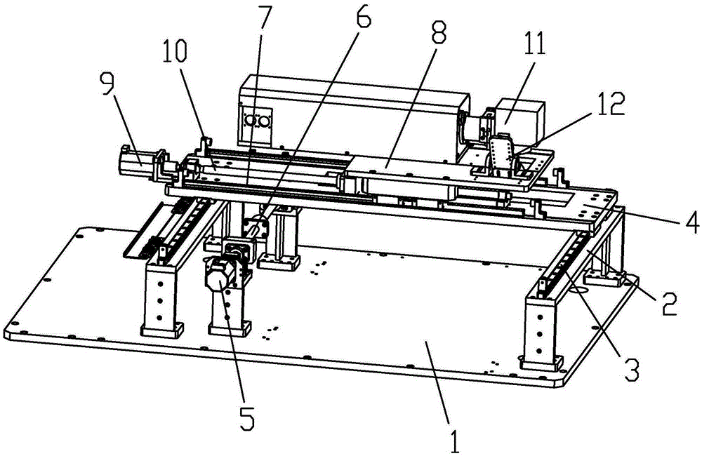
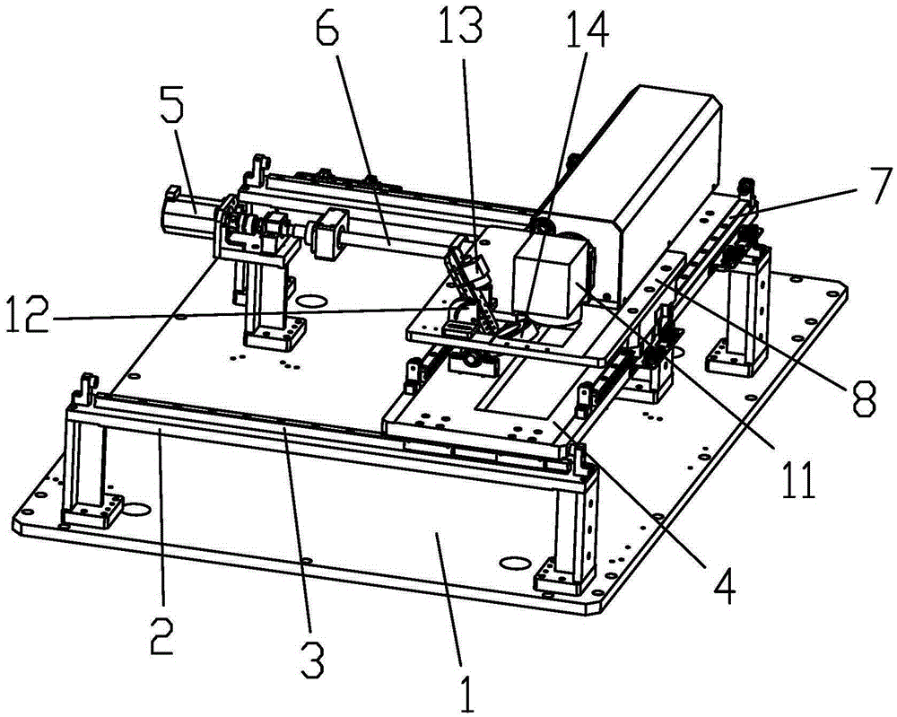
[0012] see figure 1 and figure 2 , the embodiment of the present invention includes:

[0013] A laser device of a laser marking machine, comprising: a frame plate 1 and a laser positioning mechanism fixed on the frame plate 1; the laser positioning mechanism includes a transverse mechanism and a longitudinal mechanism, and the transverse mechanism is fixed on the machine On the frame plate 1, the longitudinal mechanism is arranged on the transverse mechanism; the laser head 11 is fixed on the longitudinal mechanism, and the light source fixing frame 12 is fixed near the position of the laser head 11 on the longitudinal mechanism; the light sour...


PUM


Abstract

The invention discloses a laser device for a laser marking machine. The laser device comprises a rack plate and a laser positioning mechanism, wherein a laser head is fixed on the laser positioning mechanism, and a light source fixed mount is fixed on a position on the laser positioning mechanism, which is close to the laser head; the light source fixed mount comprises a light source fixed plate and a pair of light source fixed blocks, wherein the light source fixed blocks are symmetrically fixed on the laser positioning mechanism; a shaft hole and an annular hole are arranged in each light source fixed block, and each annular hole takes the center of the shaft hole as a center of a circle; a pair of cylindrical clamping platforms are both fixed at two sides of the light source fixed plate, and the cylindrical clamping platforms at two sides of the light source fixed plate are respectively clamped in the shaft hole and the annular hole of the corresponding light source fixed block; an annular light source is fixed at the bottom end of the light source fixed plate and is corresponding to the laser head; and a CCD (Charged Coupled Device) camera is fixed at the upper end of the light source fixed plate. Through the way, the laser device can utilize a CCD image system to position automatically, and the laser head is quickly transmitted to an appointed position to carry out marking work; and a camera side is convenient for positioning adjustment, and the flexibility is high.

Description

technical field [0001] The invention relates to the field of marking machine laser devices, in particular to a laser device for a laser marking machine. Background technique [0002] The laser marking machine is mainly used for engraving 1D / 2D text patterns on PCB printed circuit boards for high-speed engraving to achieve beautiful and clear printing effects; the laser head of the existing marking machine cannot move to the designated position quickly and accurately; The position of the CCD camera cannot be adjusted arbitrarily as needed. Contents of the invention [0003] The technical problem mainly solved by the present invention is to provide a laser device of a laser marking machine, which can automatically position the laser head by using the CCD imaging system, and quickly send the laser head to the designated position for marking work; the side-mounted camera is convenient for adjustment, positioning and code reading , high flexibility and wide application range. ...

Claims


Application Information

Patent Timeline
IPC IPC(8): H01S3/02B41J3/407
CPCH01S3/02B41J3/407
Inventor 胡锟
Owner SUZHOU WISDOM U ELECTRONICS TECH CO LTD
Why Eureka
Try Eureka