Tunnel internal induction power-drawing apparatus

A technology for inductive power collection and in tunnels, applied in circuit devices, emergency protection circuit devices, output power conversion devices, etc., can solve problems such as high energy consumption, poor effect, and limited energy, and achieve low and significant manual intervention. Economic benefit and low cost effect

Inactive Publication Date: 2016-03-23
陈威宇
View PDF5 Cites 3 Cited by
  • Summary
  • Abstract
  • Description
  • Claims
  • Application Information

AI Technical Summary

Problems solved by technology

The energy consumption of these methods is high, and the lighting of the tunnel does not need to be carried out all the time
The existing new method of power supply is to use solar energy or wind energy, but the energy provided by these two types of clean energy is limited and unstable, and the effect is not good

Method used


Image

  • Tunnel internal induction power-drawing apparatus
  • Tunnel internal induction power-drawing apparatus

Examples


Embodiment Construction

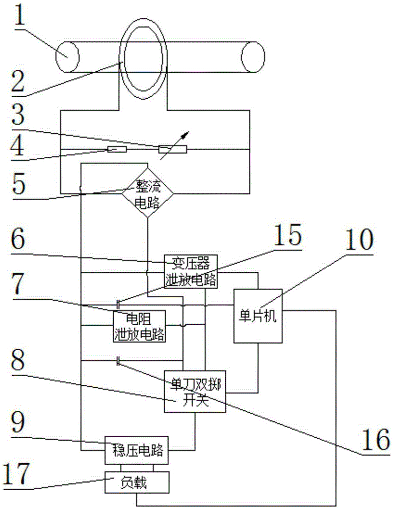
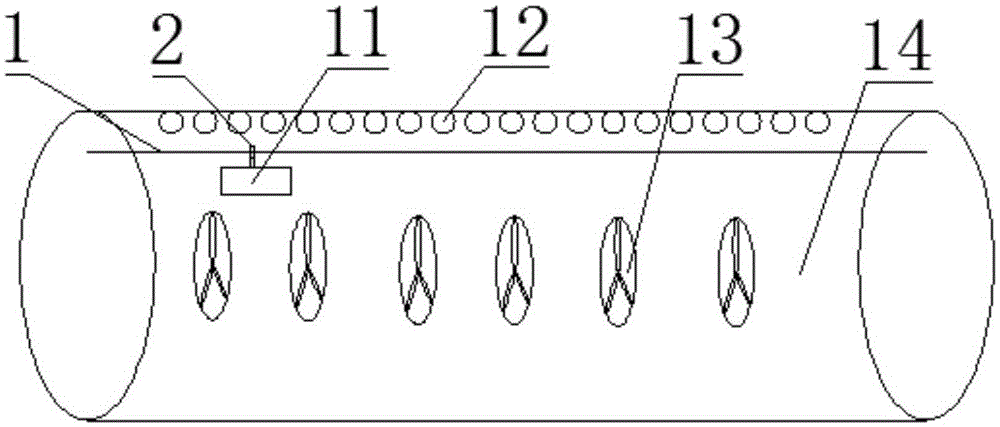
[0017] refer to figure 1 and figure 2 , an inductive power-taking device in a tunnel according to the present invention includes an inductive power-taking module 11, a variable resistor 3, a fixed resistor 4, a rectifier circuit 5, a transformer discharge circuit 6, a resistor discharge circuit 7, a single-pole double-throw switch 8, Voltage stabilizing circuit 9, single-chip microcomputer 10 and load 17, described inductive power-taking module 11 comprises variable resistance 3, fixed resistance 4, single-chip microcomputer 10, single-pole double-throw switch 8 and several circuits; There is an induction power-taking part, the induction power-taking part includes a bus bar 1 and a current transformer 2, and the current transformer 2 contains a power-taking coil; the current transformer 2 is connected in parallel with a variable resistor 3 and a fixed resistor 4, and the current transformer 2 Electrically connected to the rectifier circuit 5; the rectifier circuit 5 is elect...


PUM


Abstract

The invention discloses a tunnel internal induction power-drawing apparatus. The apparatus comprises an induction power-drawing module, a variable resistor, a fixed resistor, a rectification circuit, a transformer discharge circuit, a resistor discharge circuit, a single-pole double-throw switch, a voltage stabilizing circuit, a single-chip microcomputer and a load, wherein the induction power-drawing module comprises the variable resistor, the fixed resistor, the single-chip microcomputer, the single-pole double-throw switch and a plurality of circuits; the induction power-drawing module is internally provided with an induction power-drawing portion, the induction power-drawing portion comprises a bus and a current transformer, and the current transformer internally comprises a power-drawing coil; the current transformer is connected in parallel with the variable resistor and the fixed resistor, and the current transformer is electrically connected with the rectification circuit; and the voltage stabilizing circuit is connected in parallel with the load. According to the invention, electric energy of a high-voltage line is obtained by use of a non-contact mode, control is performed by the single-chip microcomputer, artificial intervention is low, and the apparatus can provide a stable power supply source, prolongs the service life of equipment, is quite low in cost and fully utilizes electric energy resources.

Description

【Technical field】 [0001] The invention relates to the technical field of electric power, in particular to the technical field of non-contact power-taking equipment and corresponding load equipment on high-voltage lines. 【Background technique】 [0002] With the rapid development of my country's economy, all walks of life have an increasing demand for electric power, and the requirements for the stability, uninterrupted and shock recovery of the provided electric energy are also increasing day by day. As the lifeline of the power system, the safety and stability of high-voltage transmission lines and supporting equipment also put forward high requirements. There are a large number of equipment circuits that use non-contact induction power collection to stably control high-voltage lines, and can achieve self-protection of high-voltage lines without the help of external energy such as wind and solar energy. Inductive power harvesting can obtain electric energy much lower than t...

Claims


Application Information

Patent Timeline
Patent Type & Authority Applications(China)
IPC IPC(8): H02J50/10H02H9/04H02M1/14
CPCH02H9/045H02M1/14
Inventor 陈威宇
Owner 陈威宇
Why Eureka
Try Eureka