
Stator assembly for eddy current retarder and eddy current retarder

A technology of eddy current retarder and stator assembly, which is applied in the field of automotive parts, can solve problems affecting vehicle passability, and achieve the effect of increasing the torque of the retarder

Active Publication Date: 2016-03-23
TELMA AUTOMOBILE BRAKING SYST SHANGHAI
View PDF4 Cites 0 Cited by
  • Summary
  • Abstract
  • Description
  • Claims
  • Application Information

AI Technical Summary

Problems solved by technology

In the prior art, since the retarder is usually installed at the chassis position of the car, if the chassis position of the car itself is low, the retarder will affect the trafficability of the vehicle when it is installed on the vehicle

Method used


Image

  • Stator assembly for eddy current retarder and eddy current retarder
  • Stator assembly for eddy current retarder and eddy current retarder
  • Stator assembly for eddy current retarder and eddy current retarder

Examples


Embodiment approach

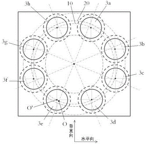
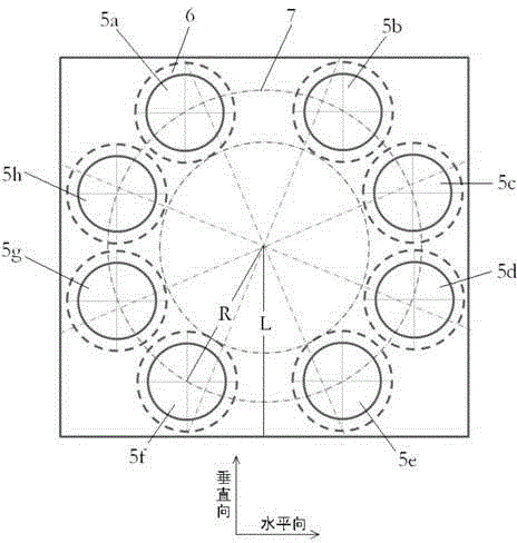
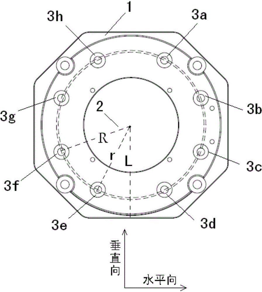
[0030] The stator assembly of the eddy current retarder provided by the present invention is also composed of 8 or 6 magnetic poles, wherein the distance from the two lowest poles to the center of the circle is r, and the distance from the rest of the poles to the center of the circle is greater than or equal to r . figure 1 It is the first embodiment of the eddy current retarder provided by the present invention, such as figure 1 Therefore, the magnetic poles 3e and 3d are located at the bottom of the retarder stator assembly. The distance between the circumference of the magnetic poles 3e and 3d and the center of the circle is r. In this way, compared with the prior art, when the retarder is installed on the vehicle, the space dimension of the retarder is still L, which remains unchanged. The distance from the circumference of the magnetic poles 3b, 3c, 3f, 3g, 3a and 3h to the center of the circle is R, and R is greater than r. The formula for calculating the total torqu...


PUM


Abstract

The invention discloses a stator assembly for an eddy current retarder, the stator assembly being used for increasing the torque without an increase on the height of the eddy current retarder. The stator assembly includes a plurality of magnetic poles fixed to a stator disc. Each magnetic pole is formed by a pole column and a coil that is wound around the outer side of the pole column. The magnetic poles include a first magnetic pole group and a second magnetic pole group. The first magnetic pole group is positioned in a first circumference that takes the center of the eddy current retarder as a center of circle. The second magnetic pole group is positioned in a second circumference that takes the center of the compact eddy current retarder as a center of circle. The radius of the first circumference is smaller than that of the second circumference.

Description

technical field [0001] The invention relates to an automobile component, in particular to a stator assembly and an eddy current retarder for an eddy current retarder. Background technique [0002] The eddy current retarder is an auxiliary braking device for automobiles. The device is installed between the car drive axle and the gearbox, and realizes non-contact braking through the principle of electromagnetic induction. The eddy current retarder can provide a strong braking torque in a fairly wide speed range, thereby avoiding safety hazards such as vehicle deviation, traditional brake failure and tire blowout, so it is widely used in motor vehicles, especially large machines on the train. [0003] The most common eddy current retarder in the prior art consists of a rotor, a stator assembly, a rotor adjusting gasket and a support frame. The stator assembly is usually composed of an even number of magnetic poles arranged on the stator disk in a certain positional relations...

Claims


Application Information

Patent Timeline
Patent Type & Authority Applications(China)
IPC IPC(8): H02K1/14H02K49/04
Inventor 刘增岗章立文
Owner TELMA AUTOMOBILE BRAKING SYST SHANGHAI
Learn More