Photovoltaic panel mounting structure

An installation structure and photovoltaic panel technology, applied in the field of solar photovoltaic panels, can solve the problems of inconvenient adjustment of the formed angle, inconvenient maintenance and maintenance, low installation efficiency of photovoltaic panels, etc., and achieve the effects of increasing power generation and convenient installation.

Inactive Publication Date: 2016-03-23
浙江电腾云光伏科技有限公司
View PDF0 Cites 11 Cited by
  • Summary
  • Abstract
  • Description
  • Claims
  • Application Information

AI Technical Summary

Problems solved by technology

In the process of people exploring renewable resources, it is found that solar energy resources are renewable resources that can be used. It has the advantages of non-pollution, clean, environmentally friendly, and renewable. The most typical ones are solar photovoltaic power generation, solar heating, etc. At present, when using solar energy to generate electricity, photovoltaic panels must be used. In photovoltaic power generation systems, a large number of photovoltaic panels are often required. The panels are fastened to the bracket by screws one by one, so there are disadvantages of low installation efficiency of photovoltaic panels, inconvenient repair and maintenance, and after the current photovoltaic panels are installed, the angle formed between them and the sunlight is impossible. Adjustable, which will affect the light effect of the photovoltaic panel, which will affect the power generation of the photovoltaic panel

Method used


Image

  • Photovoltaic panel mounting structure
  • Photovoltaic panel mounting structure
  • Photovoltaic panel mounting structure

Examples


Embodiment Construction

[0012] The installation structure of the photovoltaic panel of the present invention will be further described in detail in conjunction with the accompanying drawings and specific embodiments:

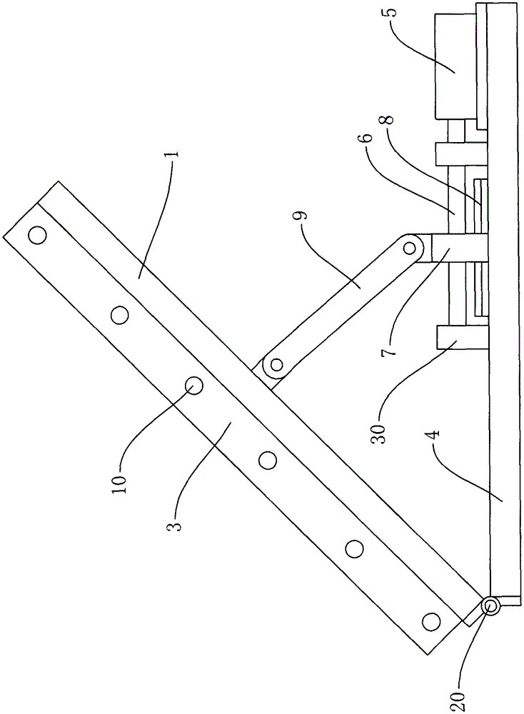
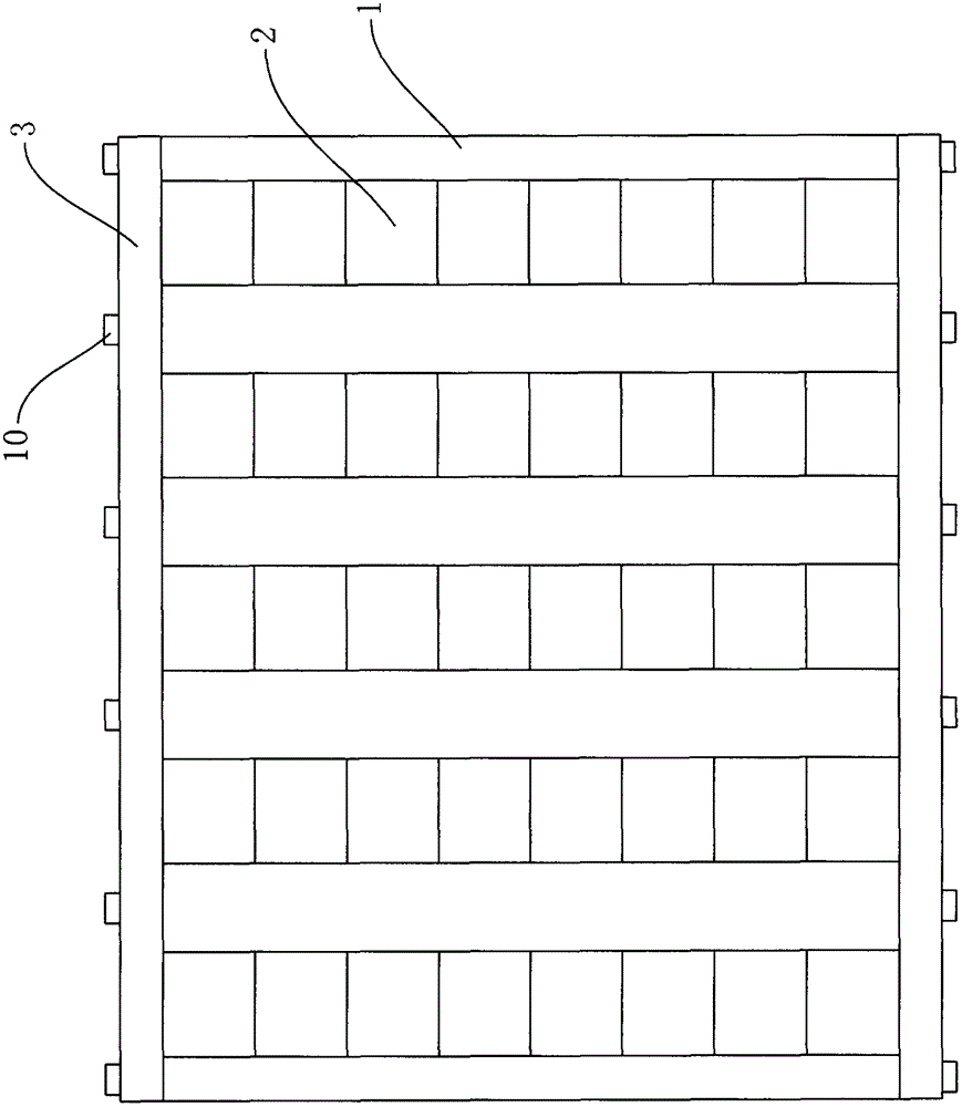
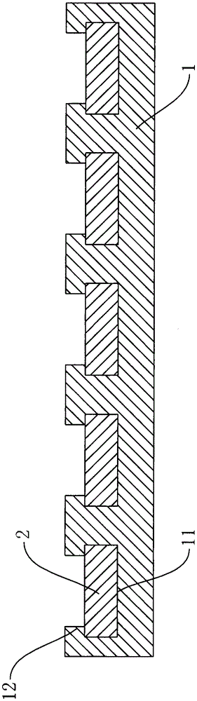
[0013] Such as figure 1 , figure 2 with image 3 The installation structure of the photovoltaic panel shown includes a photovoltaic panel assembly and a bracket assembly. The photovoltaic panel assembly includes a support plate 1. Several parallel grooves 11 are arranged on the upper end surface of the support plate 1, and each groove 11 is embedded There are several photovoltaic panels 2 distributed along the length direction of the groove 11, and the side wall of each groove 11 is provided with a flange 12 extending to the middle of the groove 11 for pressing the photovoltaic panel 2, and the supporting plate 1 A baffle 3 to prevent the photovoltaic panel 2 from slipping out of the groove 11 is fixed on the side of the frame. The bracket assembly includes a bottom plate 4. One end...


PUM


Abstract

The invention discloses a photovoltaic panel mounting structure, which comprises a photovoltaic panel assembly and a support assembly, wherein the photovoltaic panel assembly comprises a support plate; the upper end surface of the support plate is provided with a plurality of parallelly-distributed grooves; each groove is internally embedded with a plurality of photovoltaic panels distributed along the groove length direction; the side wall of each groove is provided with a folded edge extending towards the middle part of the groove for pressing the photovoltaic panel; the support assembly comprises a bottom plate; one end of the bottom plate is hinged with one end of the support plate; a motor is fixed on the bottom plate; the output shaft of the motor is connected with a screw rod; two ends of the screw rod are in rotating connection with a pair of bearings fixed on the bottom plate; a sliding block is in screw connection onto the screw rod; the bottom plate is provided with a sliding rail; the sliding block is connected onto the sliding rail in a sliding mode; a support rod is hinged at the back part of the support plate; and one end, far away from the support plate, of the support rod is hinged with the sliding block. The photovoltaic panel mounting structure has the advantages that the mounting efficiency is high; the maintenance and the repair are convenient; and the angle formed between the photovoltaic panel and the sunlight can be flexibly adjusted.

Description

Technical field: [0001] The invention belongs to the technical field of solar photovoltaic panels, and relates to a photovoltaic panel installation structure. Background technique: [0002] With the continuous development of social economy, the demand for resources of the whole society is increasing, and the resources on the earth are limited, most of the resources are non-renewable resources, so the whole society urgently needs to develop renewable resources. In the process of people exploring renewable resources, it is found that solar energy resources are renewable resources that can be used. It has the advantages of non-pollution, clean, environmentally friendly, and renewable. The most typical ones are solar photovoltaic power generation, solar heating, etc. At present, when using solar energy to generate electricity, photovoltaic panels must be used. In photovoltaic power generation systems, a large number of photovoltaic panels are often required. The panels are fast...

Claims


Application Information

Patent Timeline
Patent Type & Authority Applications(China)
IPC IPC(8): H02S20/30
CPCH02S20/00Y02E10/50
Inventor 沈晓强
Owner 浙江电腾云光伏科技有限公司
Why Eureka
Try Eureka