Display device

A technology for display devices and light exit surfaces, applied in light guides, optics, and filters for photography, etc., can solve problems such as uneven brightness and achieve the effect of reducing uneven brightness

Inactive Publication Date: 2016-03-23
SHARP KK
View PDF7 Cites 46 Cited by
  • Summary
  • Abstract
  • Description
  • Claims
  • Application Information

AI Technical Summary

Problems solved by technology

For example, in the case of using an edge-lit backlight, there is a problem that brightness unevenness occurs around the non-display area.

Method used


Image

  • Display device
  • Display device
  • Display device

Examples


no. 1 Embodiment approach >

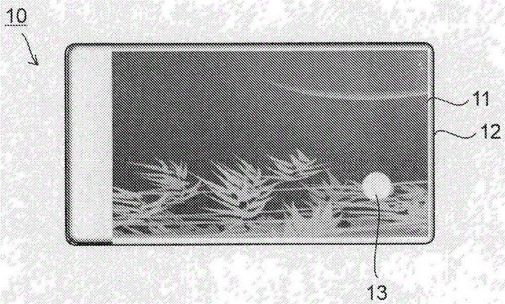
[0042] figure 1 It is a plan view of the display device of the first embodiment. This display device 10 is a smartphone and includes a display unit 11 and a housing 12 surrounding the display unit 11 . Furthermore, a non-display area 13 in which video is not displayed is formed in a part of the display unit 11 . In addition, the number of non-display regions 13 is not limited, and two or more may be formed.

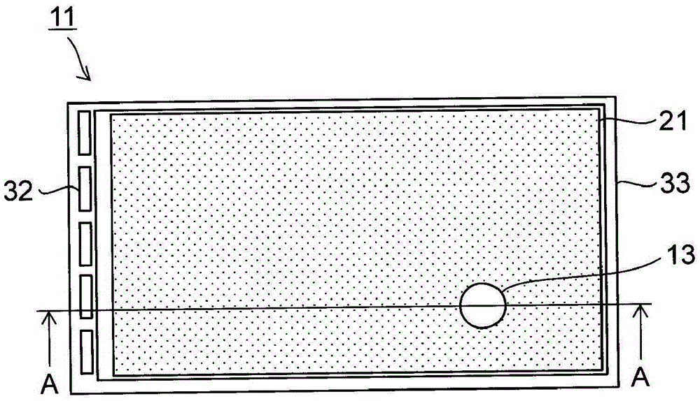
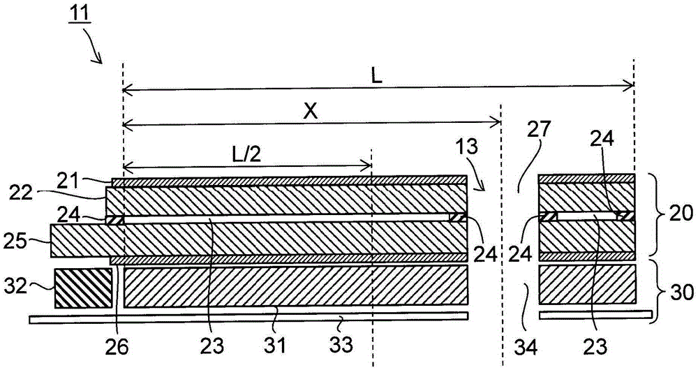
[0043] figure 2 is a plan view showing the configuration of main parts of the display unit 11, image 3 yes figure 2 An example of the A-A line sectional view. The display unit 11 includes: a liquid crystal panel 20 which is a gate device; and an edge-light type backlight 30 .

[0044] The liquid crystal panel 20 is composed of laminating an upper polarizing plate 21, an upper substrate 22 sandwiching a liquid crystal layer 23, a liquid crystal layer 23, a sealing member 24 sealing the liquid crystal layer 23, and a lower side sandwiching the liquid crystal layer...

no. 2 Embodiment approach >

[0059] Image 6 A cross-sectional view is shown in , which shows the configuration of main parts of the display unit in the display device according to the second embodiment. The second embodiment is different from the first embodiment in that there is no hole portion 27, and the other configurations are the same as those of the first embodiment.

[0060] Such as Image 6 As shown, the liquid crystal panel 20 has no holes formed therein. The portion of the liquid crystal panel 20 facing the opening 34 is configured to be normally white (transparent when a voltage is applied) or to be transparent when a voltage is applied to obtain transmittance. With such a configuration, the non-display region 13 also has transmittance as in the first embodiment. Therefore, also in the second embodiment, the same effect as that of the first embodiment can be obtained.

no. 3 Embodiment approach >

[0062] Figure 7 A sectional view is shown in , which shows the configuration of main parts of the display unit in the display device according to the third embodiment. The third embodiment differs from the first embodiment in that the hole portion 27 is formed only in the lower polarizing plate, and the other configurations are the same as those of the first embodiment.

[0063] Such as Figure 7 As shown, the hole portion 27 is formed by penetrating through the portion of the lower polarizing plate 26 that is opposed to the opening portion 34 . Also in this embodiment, as in the second embodiment, the portion of the liquid crystal panel 20 facing the opening 34 has a normally white structure or a structure that becomes transparent by voltage application in order to obtain transmittance. With such a configuration, the non-display region 13 also has transmittance as in the first embodiment. Therefore, also in the third embodiment, the same effect as that of the first embodi...


PUM


Abstract

The present invention reduces brightness unevenness at the periphery of a non-display region in a display device that uses an edge-type backlight by means of a display device (10) being provided with a liquid crystal panel (20), a light guide plate (31), which has the surface opposing the liquid crystal panel (20) as the light exit surface and one lateral surface other than the light exit surface and the surface opposite the light exit surface as the light entrance surface, a light source unit (32), which opposes the light entrance surface, and an opening (34) that pierces the light guide plate (31) from the light exit surface to the surface opposite the light exit surface, the configuration being such that the length (X) from the light entrance surface to the center of the opening (34) is at least 1/2 the length (L) from the light entrance surface to the lateral surface opposite the light entrance surface.

Description

technical field [0001] The present invention relates to a display device having a non-display area such as a window within a display area. Background technique [0002] Display devices using optical shutter devices such as liquid crystal panels and MEMS (Micro Electro Mechanical Systems) have backlights, and side-light type (edge-light) backlights are preferable due to the demand for thinner thickness in recent years. Furthermore, it has been proposed to form a transparent window portion (non-display area) in a part of the display area by applying such a display device. [0003] For example, Patent Document 1 discloses a wiring method of gate signal lines and drain signal lines for forming a non-display area. [0004] prior art literature [0005] patent documents [0006] Patent Document 1: JP-A-2009-47902 Contents of the invention [0007] The problem to be solved by the invention [0008] However, Patent Document 1 does not disclose a backlight. For example, ...

Claims


Application Information

Patent Timeline
Patent Type & Authority Applications(China)
IPC IPC(8): G02B6/00
CPCG02B6/00G02B6/0045G02F1/13318G02F1/133512G02F1/133615G03B11/04G03B15/03G02F1/133388G02B6/0053G02B6/0061G02B6/0088G02B26/04
Inventor 石田壮史结城龙三渡边寿史
Owner SHARP KK
Why Eureka
Try Eureka