
Three-level centrifugal corn grinder preventing feed from being bridged and grinding method

A pulverizer and secondary pulverization technology, applied in grain processing and other directions, can solve the problems of low pulverization efficiency, excessive power consumption, incomplete corn pulverization, etc., and achieve the effect of improving pulverizing efficiency, reducing pulverizing time, and completely pulverizing and grinding.

Active Publication Date: 2016-03-30
WEIFANG UNIV OF SCI & TECH
View PDF5 Cites 14 Cited by
  • Summary
  • Abstract
  • Description
  • Claims
  • Application Information

AI Technical Summary

Problems solved by technology

Nowadays, most of the mainstream jaw crushers and hammer crushers in the market are intermittent motion mechanisms, which have the disadvantages of low crushing efficiency and incomplete crushing of corn.
Especially in the process of long-term use, a lot of corn powder is often stuck in the crushing chamber of the traditional grinder due to too much humidity, which further affects the crushing effect of the grinder
The newly popular electromagnetic pulverizer uses the principle of electromagnetic vibration to directly drive the vibrating pipe to vibrate and hit materials at high speed after power-on, which can overcome the shortcomings of traditional mechanical pulverizers of uneven crushing, but due to excessive power consumption, it is only suitable for small batches. The preparation of the corn flour sample can not be applied to the actual large amount of corn grinding work

Method used


Image

  • Three-level centrifugal corn grinder preventing feed from being bridged and grinding method
  • Three-level centrifugal corn grinder preventing feed from being bridged and grinding method
  • Three-level centrifugal corn grinder preventing feed from being bridged and grinding method

Examples


Embodiment Construction

[0025] Below in conjunction with embodiment, further illustrate the present invention.

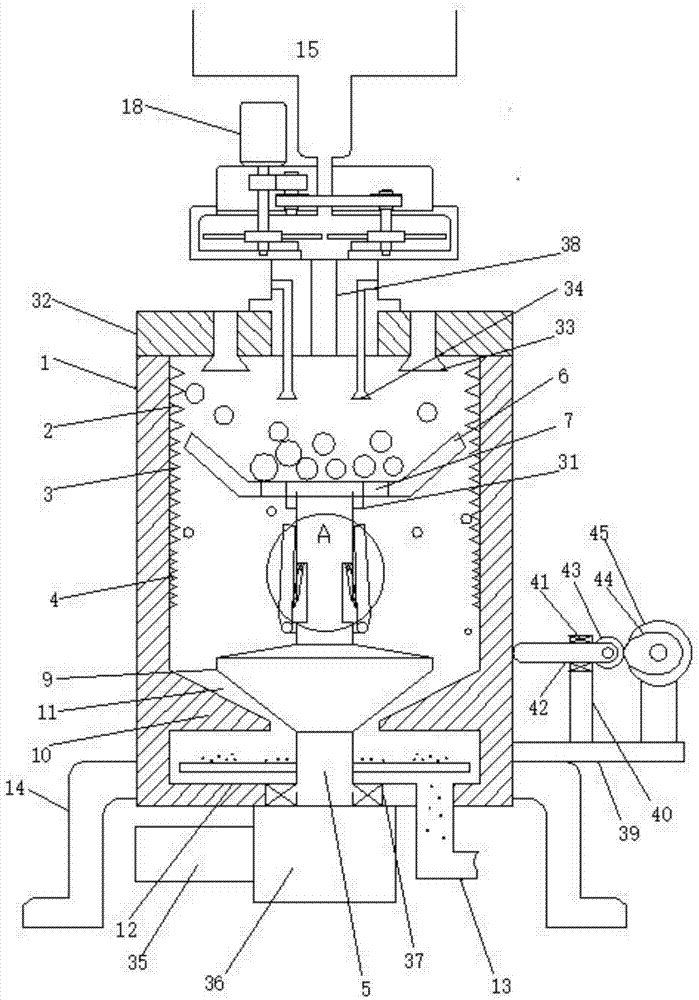
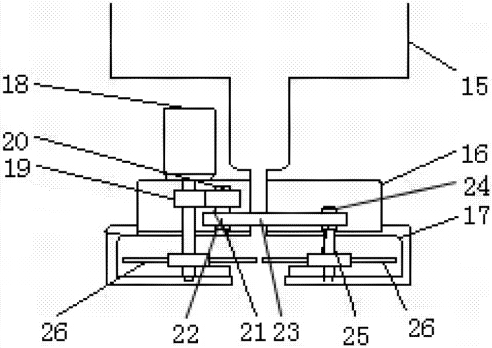
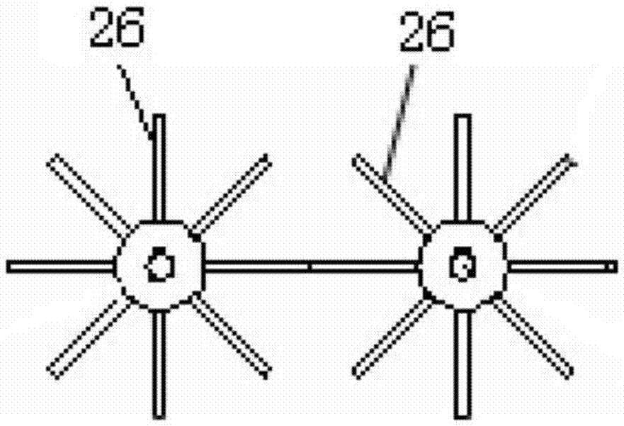
[0026] see Figure 1-Figure 5 , the present invention includes a feeding mechanism, the feeding mechanism communicates with the crushing barrel 1 through a blanking channel 38, and the inner wall of the crushing barrel 1 is sequentially provided with a primary crushing tooth 2, a secondary crushing tooth 3 and a third crushing tooth from top to bottom. stage crushing teeth 4, the crushing barrel 1 is provided with a main shaft 5, the top of the main shaft 5 is provided with a primary rotating pallet 6, and the primary rotating pallet 6 is provided with a primary powder falling port 7, and the primary shaft The middle part of the cylinder 5 is provided with a cylinder installation groove 8, and a secondary crushing mechanism is arranged in the cylinder installation groove 8, and an upper cone mill 9 is arranged on the lower side of the main shaft 5, and the side wall of the crushing bucket ...


PUM


Abstract

The invention provides a three-level centrifugal corn grinder preventing feed from being bridged and a grinding method. The corn grinder comprises a conveying mechanism, and is characterized in that the conveying mechanism is communicated with a grinding barrel, and first-level grinding teeth, second-level grinding teeth and third-level grinding teeth are sequentially arranged on the inner wall of the grinding barrel from top to bottom; a main shaft is arranged in the grinding barrel, first-level rotating supporting plates are arranged on the top of the main shaft and provided with first-level powder falling ports, air cylinder installing grooves are formed in the middle of the main shaft, and second-level grinding mechanisms are arranged in the air cylinder installing grooves; an upper cone grinder is arranged on the lower side of the main shaft, a lower cone grinder used in cooperation with the upper cone grinder is arranged on the side wall of the grinding barrel, and a conical grinding cavity is formed between the upper cone grinder and the lower cone grinder; and powder scraping pulp is arranged on the lower side of the lower cone grinder, a powder discharging pipeline is arranged at the bottom of the grinding barrel, and ground feet are arranged on the outer wall of the grinding barrel.

Description

technical field [0001] The invention relates to the field of electric control machinery, in particular to a three-stage centrifugal corn pulverizer and a pulverization method for preventing feed bridging. Background technique [0002] Corn crushing refers to the crushing of threshed corn kernels by physical means to turn them into corn flour in preparation for subsequent deep processing. Nowadays, most of the mainstream jaw crushers and hammer crushers in the market are intermittent motion mechanisms, which have the disadvantages of low crushing efficiency and incomplete crushing of corn. Especially in the process of long-term use, a lot of corn powder often sticks to the crushing chamber of the traditional pulverizer due to being too wet, which further affects the crushing effect of the pulverizer. The newly popular electromagnetic pulverizer uses the principle of electromagnetic vibration to directly drive the vibrating pipe to vibrate and hit materials at high speed afte...

Claims


Application Information

Patent Timeline
Patent Type & Authority Applications(China)
IPC IPC(8): B02C19/00B02C2/00B02C23/02
CPCB02C2/00B02C19/0018B02C23/02
Inventor 黄长永
Owner WEIFANG UNIV OF SCI & TECH
Learn More