Supercharge Your Innovation With Domain-Expert AI Agents!

A Chipless Cutting Machine for Irradiation Boxes

A technology of irradiation box and cutting machine, which is applied in the direction of metal processing machinery parts, clamping, support, etc., can solve the problem of chip-free cutting, etc., and achieve the effect of compact structure, stable operation and good safety

Active Publication Date: 2017-06-23
INST OF NUCLEAR PHYSICS & CHEM CHINA ACADEMY OF
View PDF5 Cites 0 Cited by
  • Summary
  • Abstract
  • Description
  • Claims
  • Application Information

AI Technical Summary

Problems solved by technology

[0004] In order to solve the problem that the isotope target cutting machine in the prior art cannot realize the chip-free cutting of the horizontally placed ultra-long (such as about 1m) circular, especially square, isotope irradiation boxes, the present invention provides an isotope target cutting machine. Irradiation box chipless cutting machine

Method used


Image

  • A Chipless Cutting Machine for Irradiation Boxes
  • A Chipless Cutting Machine for Irradiation Boxes
  • A Chipless Cutting Machine for Irradiation Boxes

Examples


Embodiment 1

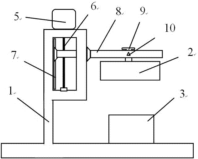
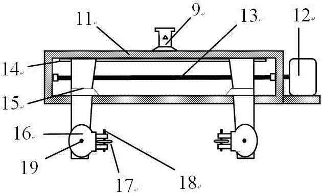
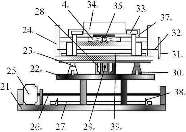
[0031] figure 1 It is a schematic layout diagram of the overall structure of an irradiation box chipless cutting machine of the present invention, figure 2 It is a schematic diagram of the cross-section structure of the cutting mechanism in the present invention, image 3 It is a schematic diagram of the cross-section structure of the tooling table in the present invention, Figure 4 It is a schematic top view of the tooling platform in the present invention, Figure 5 It is a schematic diagram of the longitudinal section structure of the cutting mechanism in the present invention, Figure 6 It is a schematic top view of the clamping platform in the present invention, Figure 7 It is a schematic diagram of the longitudinal section structure of the clamping platform in the present invention, Figure 8 It is a schematic diagram of the longitudinal section structure of the square irradiation box slot in the present invention, Figure 9 It is a schematic diagram of the longi...

Embodiment 2

[0048] Figure 9 It is a schematic diagram of the longitudinal section structure of the circular irradiation box slot in the present invention. The structure of this embodiment is the same as that of Example 1, the difference is that the cylindrical irradiation box 34 in this embodiment is selected to match it The positioning of the draw-in slots 37, the positioning columns 41 at the bottom of the draw-in slots 37 of different structures are all matched with the positioning slots 40 on the lifting platform 4 faces. like Figure 9 shown.

[0049] In the present invention, the blade rest 16 can be arbitrarily arranged within 90 degrees of the horizontal direction downwards under the drive of the motor V20 to adapt to the cutting requirements of different irradiation boxes, but the blade 17 should be as close as possible to the The cut surface of the irradiation box 34 is vertical. And when the blade 17 is not set horizontally to cut a square, especially a cylindrical irradiat...


PUM


Abstract

The invention provides a chipless irradiation capsule cutting machine which comprises a workbench, a cutting mechanism, a tool stand, a sliding rack and a controller, wherein the controller is placed outside a hot room; the workbench, the cutting mechanism, the tool stand and the sliding rack are placed in the hot room; the sliding rack is horizontally arranged in the workbench; the cutting mechanism and the tool stand are arranged under the sliding rack in sequence; the tool stand is fixedly connected with the bottom of the workbench; and the workbench, the cutting mechanism and the tool stand are electrically connected with the controller respectively. Through the chipless irradiation capsule cutting machine provided by the invention, super-long (about 1 m, for example) cylindrical and square irradiation capsules for isotope production can be cut open without chips. The chipless irradiation capsule cutting machine provided by the invention has a compact structure, is suitable for being used in the hot room or a shielded working box, which has small effective operation space, to favorably cut super-long cylindrical especially square irradiation capsules, and has high operational stability and safety.

Description

technical field [0001] The invention belongs to the technical field of radioisotope preparation, and in particular relates to a chipless cutting machine for irradiation boxes. Background technique [0002] All targets for producing radioactive isotopes through reactor irradiation must be packed in metal containers and welded and sealed, especially for targets that require high power and long-term irradiation to obtain high yield or specific activity (such as mass production high specific activity 60 Co. 63 Ni, 188 Re, 238 Pu, 252 Cf and other targets) are often required to make the target because of the influence of the nuclear reaction properties and physical and chemical properties of the target and the target material, the shape and structure of the target on the safety control parameters such as thermal hydraulics of the reactor operation, etc. It is made into an irradiation box with the same or similar shape and structure as the reactor fuel element (or component),...

Claims


Application Information

Patent Timeline
Patent Type & Authority Patents(China)
IPC IPC(8): B23D79/00B23Q5/40B23Q3/06B23Q1/26
CPCB23D79/00B23Q1/626B23Q3/062B23Q5/40
Inventor 刘国平王关全陈静钟文彬陈琪萍牟婉君蹇源李兴亮李梅谢翔魏洪源何佳恒胡睿党宇峰刘飞
Owner INST OF NUCLEAR PHYSICS & CHEM CHINA ACADEMY OF
Features
  • R&D
  • Intellectual Property
  • Life Sciences
  • Materials
  • Tech Scout
  • Unparalleled Data Quality
  • Higher Quality Content
  • 60% Fewer Hallucinations
Learn More