Method of and apparatus for working structure

a technology of working structure and working cavity, which is applied in the field of working structure, can solve the problems of inefficiency of working cavity, large number of trials and errors of electron beam lithography, and inability to work cavities, so as to achieve efficient cutting and improve the efficiency of structur

Active Publication Date: 2008-05-29
TOWA
View PDF5 Cites 27 Cited by
  • Summary
  • Abstract
  • Description
  • Claims
  • Application Information

AI Technical Summary

Benefits of technology

[0021]An object of the present invention is to efficiently improve the productivity of a structure by efficiently cutting a structure having a desired number (a plurality) of cavities in a method of working a structure.

Problems solved by technology

However, the electron beam lithography requires a considerable number of trials and errors in order to obtain optimum exposure distribution, and worked cavities 106 are small.
Therefore, a mold formed by this lithography is so inferior in working efficiency that the same is not yet put into practice.
However, setup times are required for working a desired number (a large number) of cavity parts 108 (single cavities 106) respectively as hereinabove described, and a mold (split mold) having a desired number (a plurality) of cavities cannot be efficiently cut for efficiently manufacturing the optical component mold.
Therefore, the productivity of the optical component mold (structure) cannot be efficiently improved.
Consequently, the productivity of the optical component mold (structure) cannot be efficiently improved in the working of (the working method for) the optical component mold.
Further, it is remarkably difficult to precisely arrange cavities 106 formed in mold material (workpiece) 102 at a desired pitch.
In the aforementioned working, however, no sufficient desired cutting speed is obtained particularly in a case of cutting a hardly cuttable material such as cemented carbide, and hence working resistance is so increased that the working surface (concave surface, for example) cannot be mirror-finished.
In the case of working the optical component mold, therefore, the working surface formed on the mold cannot be efficiently mirror-finished, and a high-quality working surface cannot be efficiently worked.
However, such a cavity cannot be efficiently worked in the aforementioned working method employing rotation center 105 as the axis of rotation.
Thus, an optical component molding cavity having an opening of a desired shape and a nonspherical working surface cannot be efficiently worked in the working (method) of the optical component mold.

Method used


Image

  • Method of and apparatus for working structure
  • Method of and apparatus for working structure
  • Method of and apparatus for working structure

Examples


first embodiment

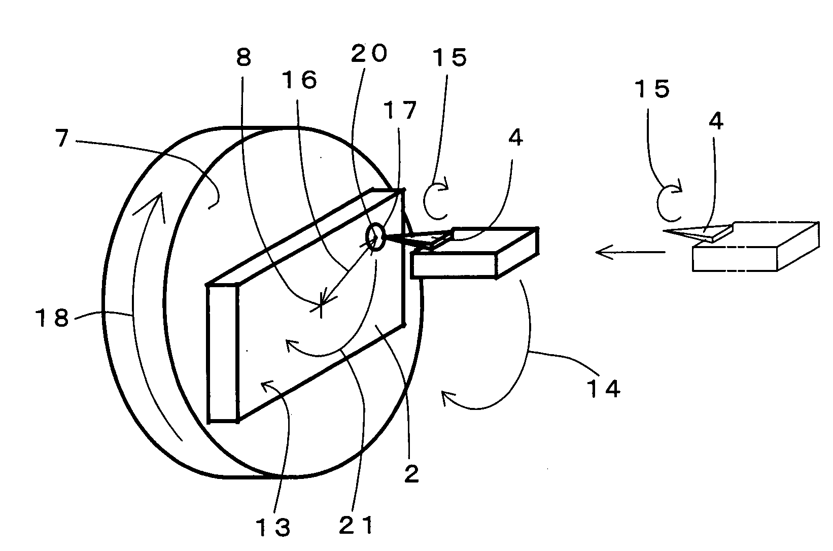
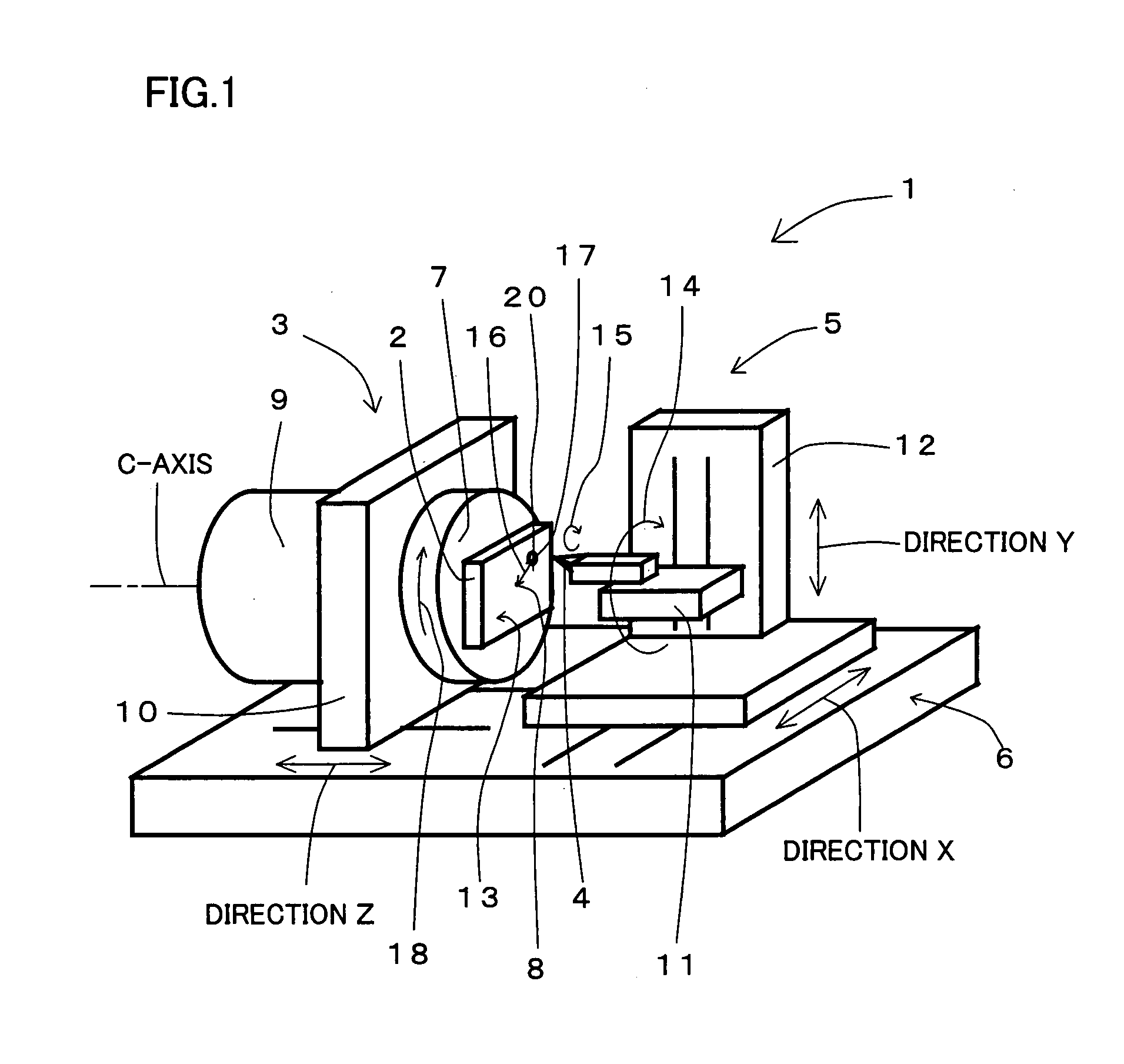
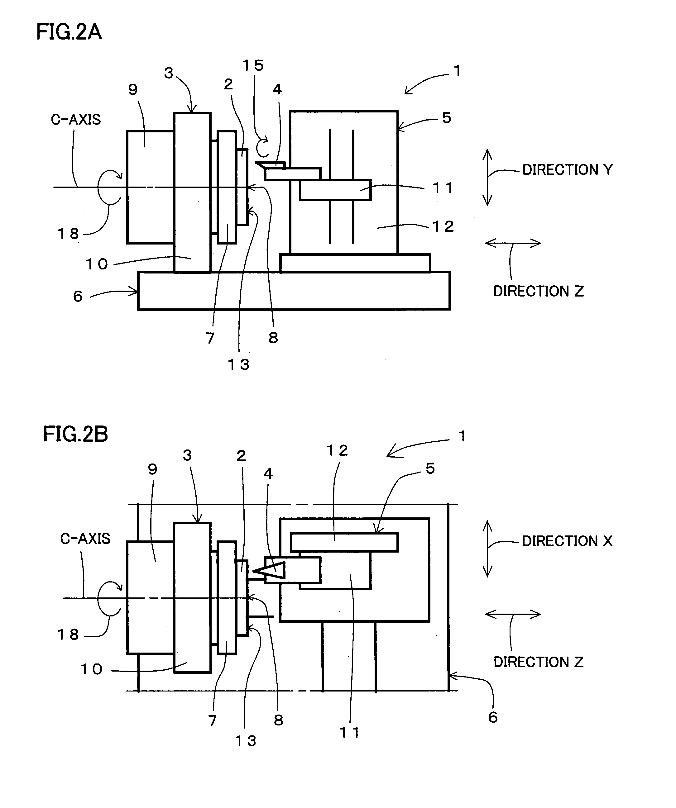
[0082]FIGS. 1, 2A and 2B show a four-spindle lathe-type cutting / working apparatus according to a first embodiment of the present invention. FIGS. 3A, 3B, 4A, 4B, 5, 6A, 6B, 7A and 7B show principal parts of the four-spindle lathe-type cutting / working apparatus according to the first embodiment of the present invention.

(Overall Structure of Lathe-Type Cutting / Working Apparatus)

[0083]The structure of a lathe-type cutting / working apparatus 1 according to the first embodiment of the present invention is described with reference to FIGS. 1, 2A and 2B.

[0084]As shown in FIGS. 1, 2A and 2B, lathe-type cutting / working apparatus 1 (four-spindle lathe-type cutting / working apparatus having X-, Y-, Z- and C-axes in FIGS. 1, 2A and 2B) according to the first embodiment of the present invention is provided with a mold material mount mechanism (workpiece mount mechanism) 3 mounted with a mold material (workpiece) 2 such as a steel material, a cutting tool mount mechanism 5 mounted with a cutting to...

second embodiment

[0238]A second embodiment of the present invention employing high-speed milling in place of working by elliptical vibration cutting is now described with reference to FIGS. 12A and 12B.

[0239]The basic structure of a lathe-type working apparatus 51 employed in the second embodiment is identical to that of cutting / working apparatus 1 according to the first embodiment. Therefore, identical portions are denoted by the same reference signs, and redundant description is not repeated.

(Structure of Lathe-Type Working Apparatus 51 According to Second Embodiment)

[0240]Lathe-type working apparatus 51 shown in FIG. 12A is provided with a mold material mount portion 7 mounted with a mold material 2 and a rotary cutting mechanism 53 having a rotary cutting tool 52 for high-speed milling.

[0241]According to the second embodiment, a rotary blade 55 provided on the forward end of rotary cutting tool 52 is employed in place of the vibration speed of elliptical vibration locus 14 according to the first...


PUM

PropertyMeasurementUnit
depth of cutaaaaaaaaaa
cutting speedaaaaaaaaaa
cutting feed rateaaaaaaaaaa

Abstract

In a method of working a structure, a mold material is mounted on a mold material mount portion of a cutting/working apparatus and rotated about the C-axis serving as the rotation center while a cutting tool is driven and moved in directions X and Y. Then, a desired position of the mold material is cut with the cutting tool at a relatively formed desired cutting speed and elliptically vibrated/cut with the cutting tool, for forming a Fresnel lens molding cavity having an opening of a desired shape and a working surface (concave surface, for example) of a desired shape. According to this method, the productivity of an optical component mold employed as the structure can be efficiently improved when the mold for molding an optical component such as a Fresnel lens is worked by cutting the mold material employed as a workpiece with the cutting tool in a four-spindle lathe-type cutting/working apparatus including X-, Y-, Z- and C-axes of rotation.

Description

[0001]This nonprovisional application is based on Japanese Patent Application No. 2006-317162 filed with the Japan Patent Office on Nov. 24, 2006, the entire contents of which are hereby incorporated by reference.BACKGROUND OF THE INVENTION[0002]1. Field of the Invention[0003]The present invention relates to a method of working a structure for working a workpiece into a structure having a cavity of a desired shape, and more particularly, it relates to a method of working an optical component mold (structure) for forming an optical component such as a Fresnel lens or an LED component by molding an optical element (electronic component) such as a light-emitting diode (LED) chip with a resin material such as silicone resin, for example.[0004]2. Description of the Background Art[0005]Working of a mold material with a conventional four-spindle lathe-type cutting / working apparatus is now described with reference to FIGS. 13A and 13B. In general, a lathe-type cutting / working apparatus 101 ...

Claims


Application Information

Patent Timeline
Patent Type & Authority Applications(United States)
IPC IPC(8): B26D7/00
CPCB23B1/00B23B29/125B23B2226/31B23B2265/16Y10T82/10B24B1/04B24B13/046Y10T82/25B23C3/00Y10T83/04Y10T83/889B29D11/00
Inventor KUNIMATSU, SHINYAONISHI, HISAYOSHIMATSUO, MAKOTO
Owner TOWA
Why Eureka
Try Eureka