
Dilation catheter assembly with bipolar cutting element

a cutting element and dilatation catheter technology, applied in the field of dilatation catheters, can solve the problems of stray currents having unintended tissue effects, monopolar devices failing to cut, and failure to cut, so as to reduce or eliminate stray currents and improve cutting. effect, capacitive coupling

Inactive Publication Date: 2007-11-15
APPL MEDICAL RESOURCES CORP
View PDF34 Cites 28 Cited by
  • Summary
  • Abstract
  • Description
  • Claims
  • Application Information

AI Technical Summary

Benefits of technology

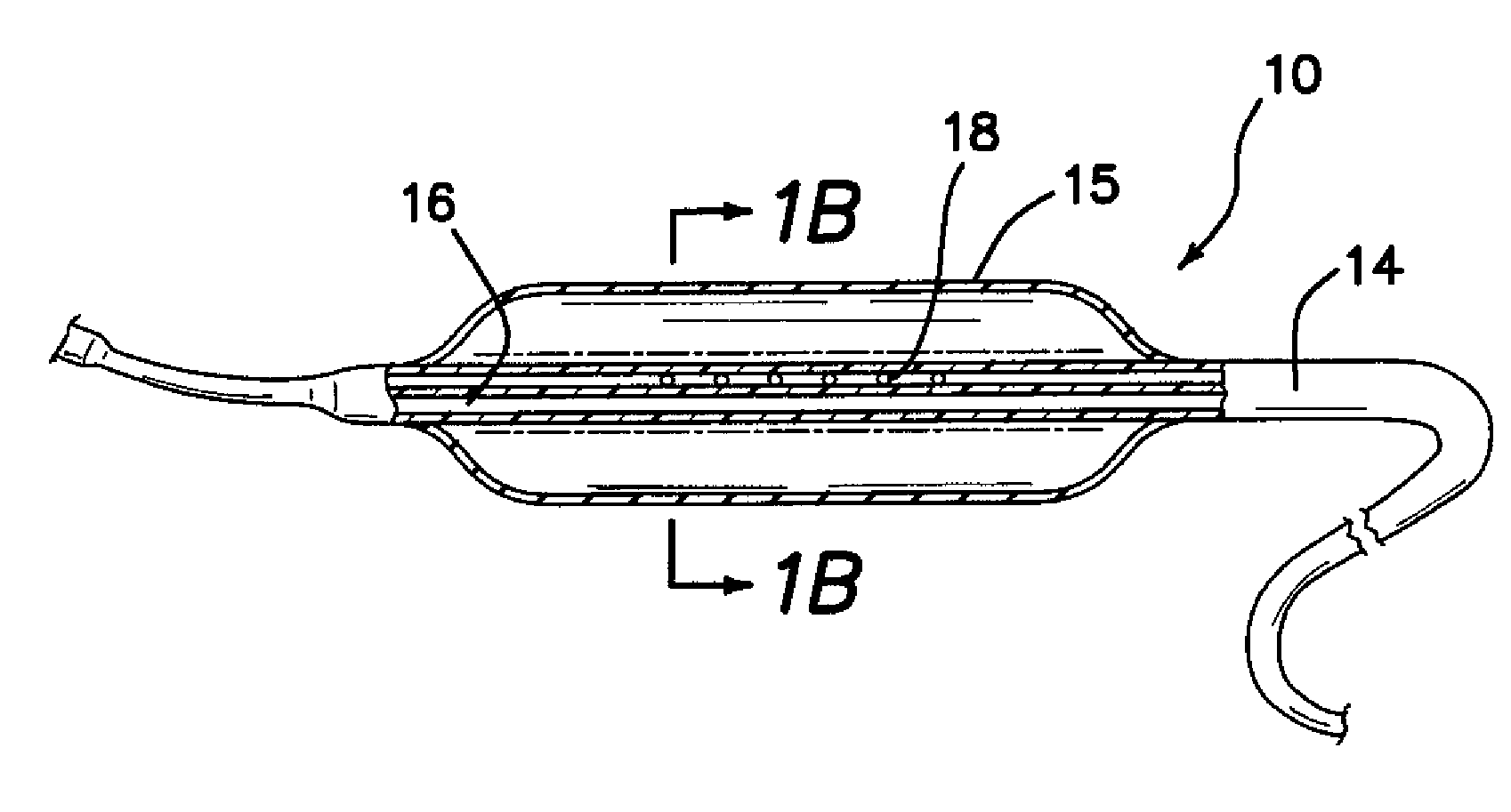
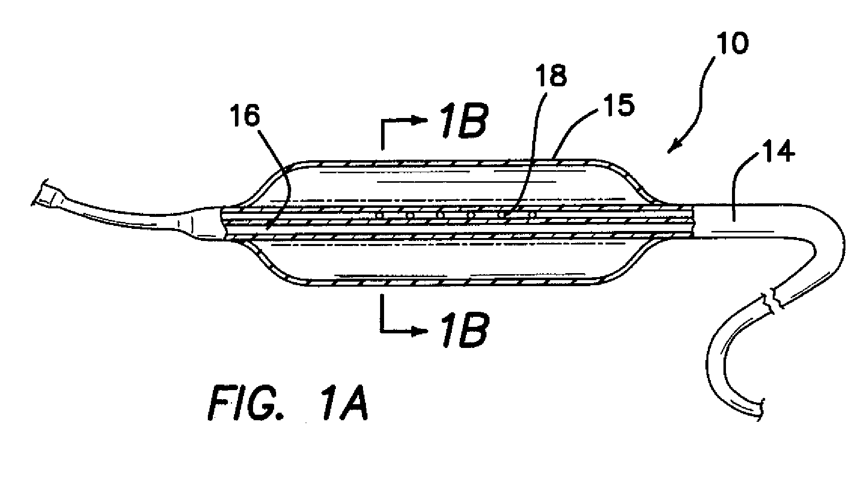
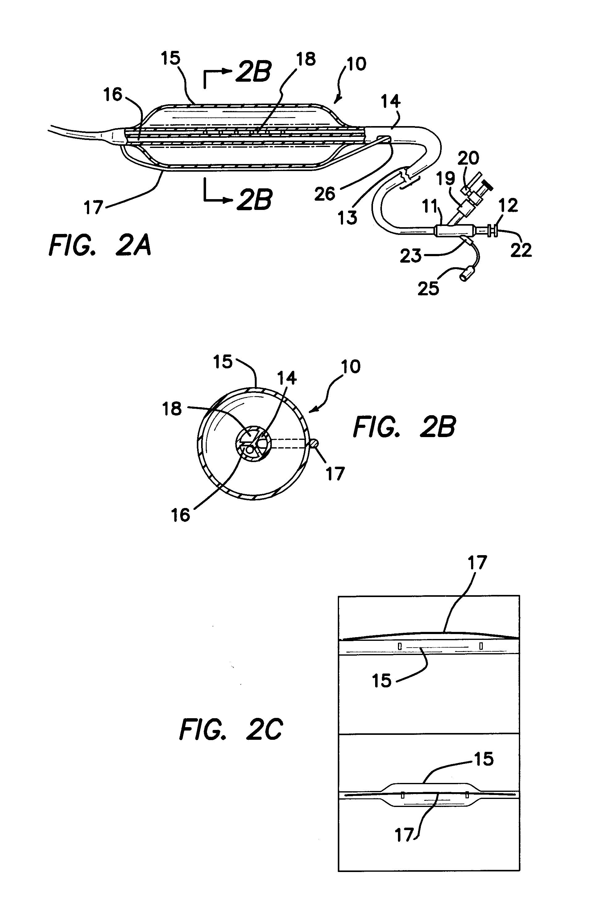
[0010]The presented invention provides a method and apparatus to overcome the drawbacks of a monopolar cutting arrangement by supplying electrical energy in a bipolar or quasi-bipolar fashion. Unlike a monopolar arrangement, in a bipolar or quasi-bipolar configuration, the electrical current will flow only through tissue between closely-spaced electrodes, resulting in improved cutting, while reducing or eliminating stray current and capacitive coupling.
[0011]The bipolar or quasi-bipolar configuration does not require a return electrode pad on the patient's skin, thus eliminating any risk of return electrode burns. Instead, the active electrodes are placed on the surgical tool in close proximity of the tissue to be affected, thereby reducing the amount of tissue exposed to electrical energy in general. In this new inventive configuration, the device has a “built-in” spark gap between the two electrodes, thus producing more efficient cutting.
[0012]Importantly, the close proximity of the active and return electrode eliminates the risk of inadvertent tissue burns. Since the electrical energy only travels between the two electrodes, only the tissue between the two electrodes is affected and inadvertent tissue damage, outside of the surgeon's field of view, can be eliminated.

Problems solved by technology

Despite the success of the monopolar electrosurgery technique, a few problems may arise during its use.
For example, in some circumstances there may be a failure to cut.
A second reason a monopolar device may fail to cut is due to the use of saline or contrast in the urinary system, for example.
In addition, stray current may have unintended tissue effects, not readily apparent to the physician.
Blood in arteries and veins can be much more conductive than the surrounding tissue and can be overheated in the process of conducting that electricity.
Finally, with monopolar electrosurgical devices, problems may arise if the surgeon activates the device in the patient without making contact with tissue.
This can cause what is known as capacitive coupling and can cause another metallic component nearby to conduct electricity to tissue and cause a burn that is not known by the surgeon.

Method used


Image

  • Dilation catheter assembly with bipolar cutting element
  • Dilation catheter assembly with bipolar cutting element
  • Dilation catheter assembly with bipolar cutting element

Examples


Embodiment Construction

[0026]Unless defined otherwise, all technical and scientific terms used herein have the same meaning as commonly understood to one of ordinary skill in the art to which this invention belongs. Although any methods, devices and materials similar or equivalent to those described herein can be used in the practice or testing of the invention, the preferred methods, devices and materials are now described.

[0027]All publications mentioned herein are incorporated herein by reference for the purpose of describing and disclosing, for example, the structures and / or methodologies that are described in the publications which might be used in connection with the presently described invention. The publications discussed above and throughout the text are provided solely for their disclosure prior to the filing date of the present application. Nothing herein is to be construed as an admission that the inventors are not entitled to antedate such disclosure by virtue of prior invention.

[0028]The fol...


PUM


Abstract

A method and apparatus for the dilatation of obstructed body vessels, orifices and conduits, combined with a controlled and regulated incision of the dilated body vessels using a bipolar or quasi-bipolar electrosurgical cutting wire arrangement is presented.

Description

CROSS-REFERENCE TO RELATED APPLICATION[0001]This application claims benefit of U.S. Provisional Application No. 60 / 747,263, filed May 15, 2006, the entire disclosure of which is hereby incorporated by reference as if set forth in full herein.FIELD OF THE INVENTION[0002]The present invention relates generally to the field of electrosurgical devices and more specifically to a dilatation catheter having an expandable member comprising a cutting element that concurrently incises body tissue in a bipolar or quasi-bipolar fashion.BACKGROUND[0003]Dilatation catheters are used to dilate body vessels, orifices and conduits, such as a constricted or obstructed ureter or urethra. Typically, a dilation catheter comprises an elongated catheter having an inflatable balloon at or near the distal end. A guide wire or other axial support means is often included to improve the ability to position the apparatus appropriately, usually visualized under fluoroscopy.[0004]Dilation catheters incorporating ...

Claims


Application Information

Patent Timeline
IPC IPC(8): A61B18/14
CPCA61B18/1492A61B2018/00214A61B2018/00285A61M2025/1086A61M29/02A61M2025/0096A61B2018/144
Inventor FALKENSTEIN, ZORANPRAVONG, BOUNHART, CHARLES C.BRUSTAD, JOHN R.NGUYEN, ERIC
Owner APPL MEDICAL RESOURCES CORP
Learn More