Self-counterboring, screw-threaded headed fastener with enlarged flanged portion or wings having cutting teeth thereon, and cutting wrench/screw gun sockets

a screw-threaded, self-counterboring technology, applied in the direction of threaded fasteners, screwing, manufacturing tools, etc., can solve the problems of inability to fixly secure or attach structural or non-structural components to the underlying fixed support or substrate, requiring costly procedural time, etc., to achieve the effect of cutting or boring

Inactive Publication Date: 2012-10-25
ILLINOIS TOOL WORKS INC
View PDF0 Cites 29 Cited by
  • Summary
  • Abstract
  • Description
  • Claims
  • Application Information

AI Technical Summary

Benefits of technology

[0005]The foregoing and other objectives are achieved in accordance with the teachings and principles of the various embodiments consistent with the present invention through the provision of a new and improved self-counterboring screw-threaded headed fastener which is provided with an enlarged circular flanged portion disposed adjacent to the head portion of the fastener. The enlarged circular flanged portion has a circumferentially arranged set of cutting teeth integrally formed upon the outer peripheral edge portion thereof for effectively cutting or boring into and through a structural or non-structural component to be affixed to an underlying fixed support or substrate whereupon the structural or non-structural component can be fixedly secured to the underlying support or substrate as a result of the screw-threaded fastener drilling and tapping its way into the underlying fixed support or substrate. In this manner, the structural or non-structural component can in fact be fixedly secured to the underlying support or substrate without requiring a bore to first be drilled within the structural or non-structural component.
[0008]The axial depth of the cutting teeth is therefore effectively decreased by the axial thickness of the hemispherical or domed-shaped steel washer. Accordingly, together with the termination of the screw threads upon the threaded shank portion of the fastener within the vicinity of the enlarged circular flanged portion, the penetration of the fastener completely through the lower-most portion of the foam core of the insulated metal panel (IMP) and into the lower steel sheet portion of the insulated metal panel (IMP) is effectively prevented. However, the tip portion of the fastener, and the lower or distal end portion of the threaded shank portion of the fastener, do in fact penetrate through the lower steel sheet portion of the insulated metal panel (IMP) and effectively tap into the underlying support or substrate such that the laminated component is able to be fixedly secured to the underlying fixed support or substrate. As a specific example, the tip portion of the headed fastener may comprise a self-drilling tip. In addition, the threaded shank portion of the headed fastener of the present invention may comprise self-tapping threads.
[0010]Alternatively, and still further, in lieu of the aforenoted fixation of the insulated metal panel (IMP) to the underlying support or substrate, a different structure, such as, for example a first wooden structural or non-structural member may be fixedly secured to a second underlying wooden structural or member or substrate, or still yet further, a wooden structural or non-structural member may be fixedly secured to an underlying steel, other metal, or concrete substrate. Still yet further, in lieu of the new and improved self-counterboring screw-threaded headed fastener, comprising the head portion, the threaded shank portion, and the enlarged circular flanged portion being fabricated as a one-piece fastener, as has been previously described, the enlarged circular flanged portion may be fabricated separately from the primary structure of the fastener, comprising the head portion and the shank portion of the fastener, and may be fixedly secured onto the shank portion of the fastener by any one of a multitude of securing techniques so as to again be disposed adjacent to the head portion of the fastener. Accordingly, the resulting composite structure is effectively the same as that of the original embodiment whereby the enlarged circular flanged portion, having the cutting teeth thereon, can operate to effectively form the washer component from the upper or top steel sheet member of, for example, an insulated metal panel (IMP). Yet still further, in lieu of the provision of the enlarged circular flanged portion upon the headed fastener, diametrically opposed wing members, having cutting teeth disposed thereon, can likewise be utilized to provide the self-countering effect for forming the bore within which the head of the headed fastener can be accommodated during insertion of the headed fastener into and through, for example, the insulated metal panel (IMP).

Problems solved by technology

These pre-drilling and cleaning procedures obviously define multi-step procedures which are tedious to perform, and necessarily mandate costly procedural time, however, they must nevertheless be performed before the self-drilling and / or self-tapping fasteners or anchors can in fact be inserted into the bores for threadedly engaging the side-wall portions of the substrate bores, or the substrates themselves, in order to, in turn, fixedly secure a particular component to the substrate.
However, if the pre-drilled bore is then effectively larger in the diametrical extent of the fastener head, the fastener would not in fact be capable of fixedly securing or attaching the structural or non-structural component to the underlying fixed support or substrate.

Method used


Image

  • Self-counterboring, screw-threaded headed fastener with enlarged flanged portion or wings having cutting teeth thereon, and cutting wrench/screw gun sockets
  • Self-counterboring, screw-threaded headed fastener with enlarged flanged portion or wings having cutting teeth thereon, and cutting wrench/screw gun sockets
  • Self-counterboring, screw-threaded headed fastener with enlarged flanged portion or wings having cutting teeth thereon, and cutting wrench/screw gun sockets

Examples


second embodiment

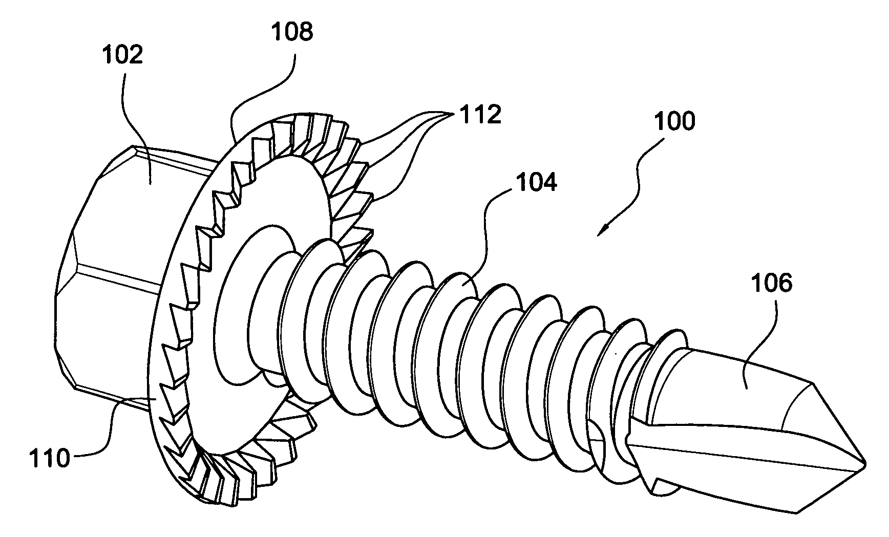
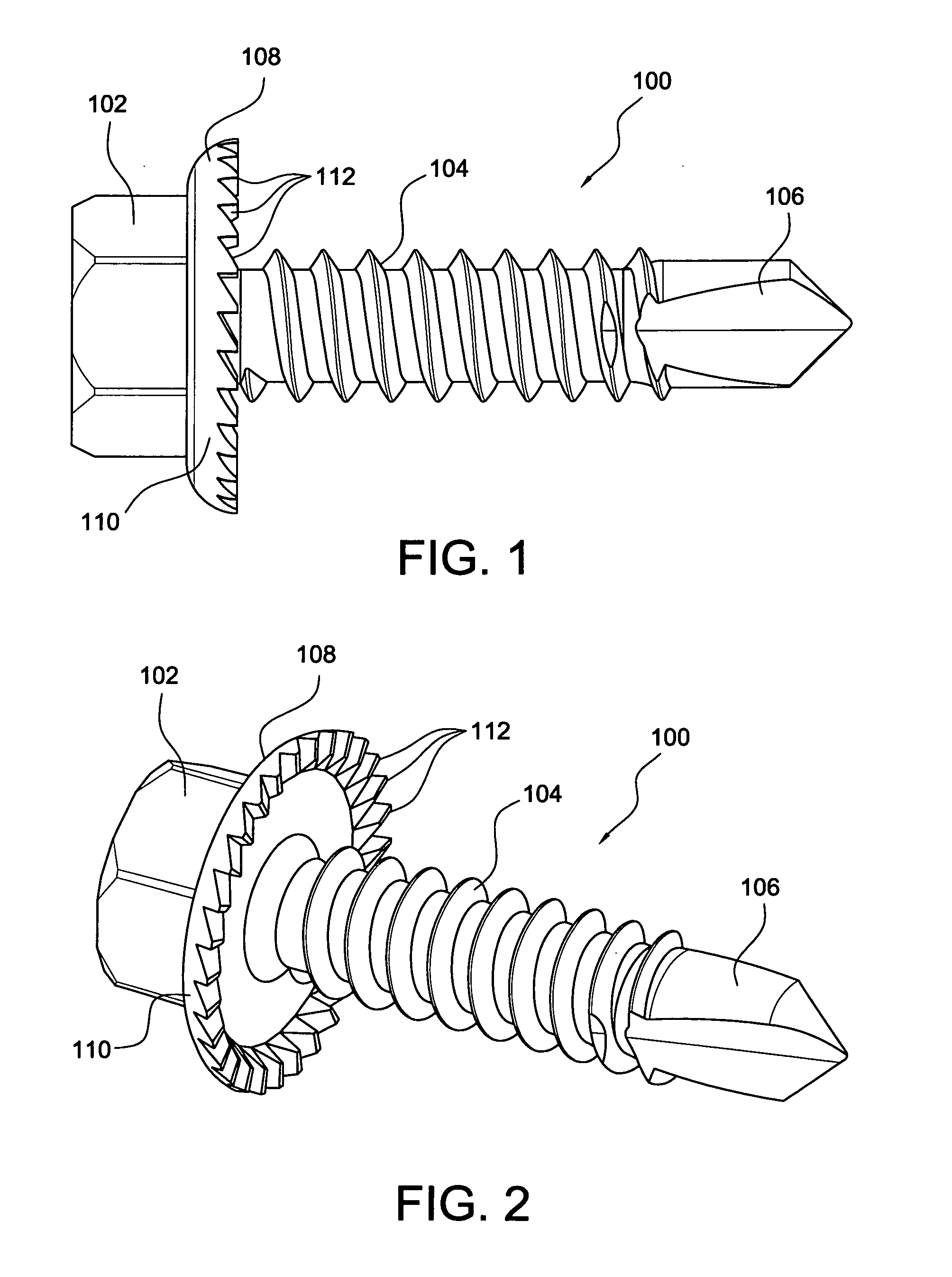
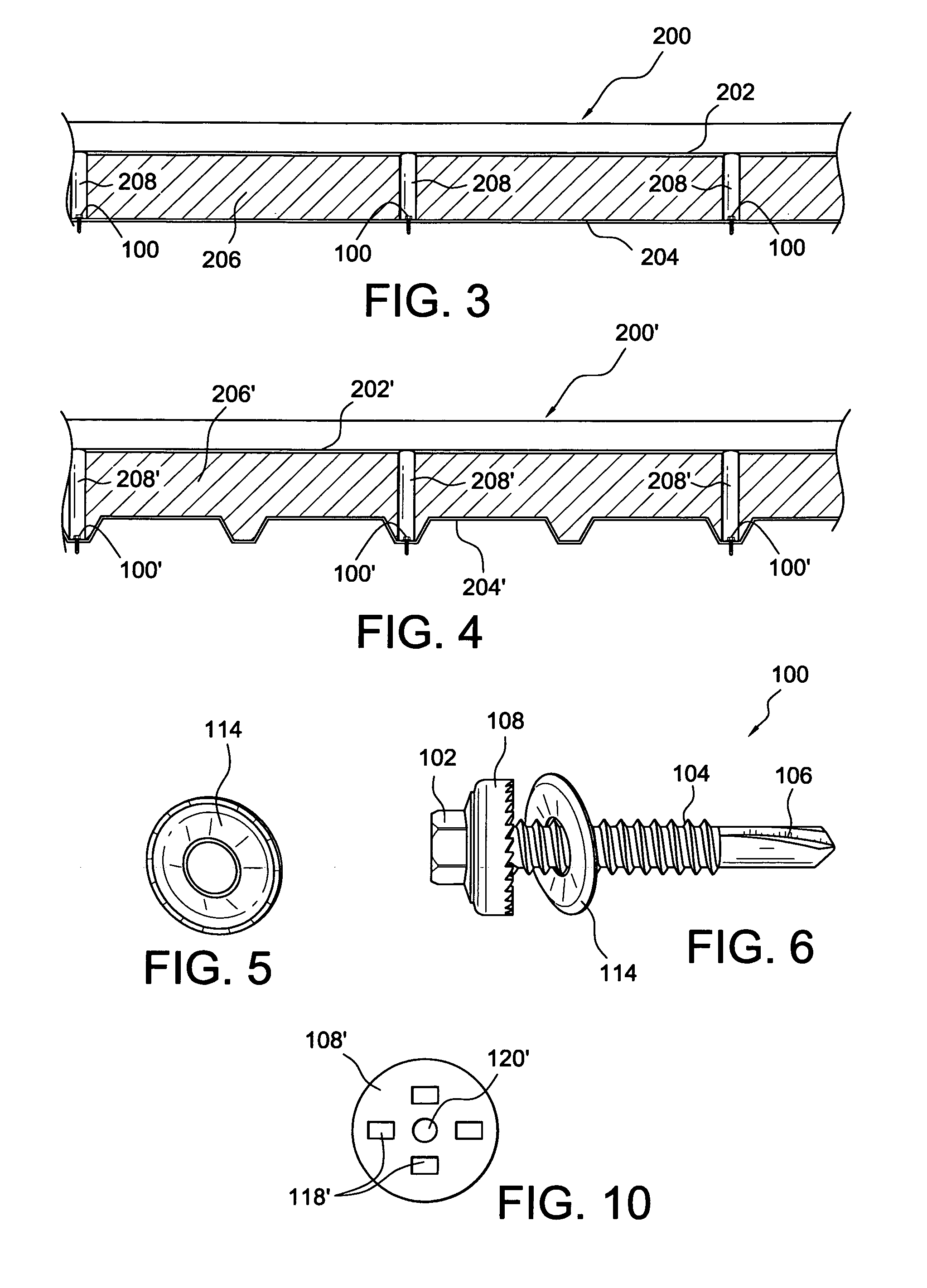
[0037]Continuing still further, while the first and second embodiment fasteners 100,300 have been previously described as being fabricated as one-piece fasteners comprising, for example, the head portions 102,302, the threaded shank portions 104,304, the tip portions 106,306, and the enlarged circular flanged portions 108,308, it is contemplated that the fasteners 100,300 can effectively be manufactured or fabricated as two piece assemblies comprising the self-drilling, self-tapping fastener per se which would include, for example, the head portion 102, the threaded shank portion 104, and the tip portion 106, and the separately fabricated enlarged circular flanged portion 108 with its cutting teeth 112 formed thereon. The manufacture or fabrication of the fastener 100 as a two-piece assembly might, in some instances, facilitate or expedite its manufacture in a relatively simplified manner. The enlarged circular flanged portion 108 would then be fixedly mounted upon the undersurface ...

first embodiment

[0039]With reference now being made to FIGS. 11 and 12, there are additionally disclosed wrench sockets, or alternatively, such structures could be screw gun sockets, which have also been constructed in accordance with the teachings and principles consistent with the present invention, and which, together with a screw-threaded fastener, can effectively accomplish the various drilling, cutting and boring operations which were capable of being achieved by means of the self-counter-boring, screw-threaded fastener 100 as disclosed within, for example, FIGS. 1 and 2. such a wrench or screw-gun socket is illustrated within FIG. 11 and is generally indicated by the reference character 400. The wrench or screw-gun socket 400 is substantially a conventional wrench or screw-gun socket for rotatably driving headed fasteners or similar structures, however, the wrench or screw gun socket 400 of the present invention has been modified for the particular purposes and objectives consistent with the...


PUM


Abstract

A self-counterboring screw-threaded headed fastener, for the threaded insertion into an underlying fixed support or substrate in order to fixedly secure a structural component, such as, for example, an insulated metal panel (IMP), to the underlying fixed support or substrate without the need for pre-drilling a bore within the insulated metal panel (IMP), in order to accommodate the screw-threaded head of the fastener, prior to the insertion of the screw-threaded fastener into and through the insulated metal panel (IMP) for fixation within and to the underlying fixed support or substrate, is disclosed. Cutting wrench or screw-gun sockets are also disclosed for similar purposes.

Description

FIELD OF THE INVENTION[0001]This patent application relates generally to screw-threaded fasteners, and more particularly to a new and improved self-counterboring, screw-threaded headed fastener for the threaded insertion into an underlying fixed support or substrate in order to fixedly secure a structural or non-structural component, such as, for example, an insulated metal panel (IMP), to the underlying fixed support or substrate without the need for pre-drilling a bore within the insulated metal panel (IMP), in order to accommodate the screw-threaded fastener head, prior to the insertion of the screw-threaded fastener into and through the insulated metal panel (IMP) for fixation within and to the underlying fixed support or substrate. A screw-threaded fastener with wing members having cutting teeth, as well as cutting wrench or screw-gun sockets are also disclosed for similar purposes.BACKGROUND OF THE INVENTION[0002]Various different types of fasteners or anchors are of course we...

Claims


Application Information

Patent Timeline
Patent Type & Authority Applications(United States)
IPC IPC(8): F16B25/10B25B13/06F16B23/00E04C2/00
CPCE04D3/3606F16B25/0031F16B25/103E04D3/3603E04F13/0875E04F13/12F16B35/065
Inventor PANASIK, CHERYL L.GONG, YONGPINGTHOMAS, LOUISTUCKER, KEVINILEA, HOREACZARKOWSKI, ANTHONY A.
Owner ILLINOIS TOOL WORKS INC
Why Eureka
Try Eureka