Rapid-releasing sleeving tool

A tool and unsleeve technology, which is applied in the field of quick-release socket tools, can solve the problems of loose sliding parts and inability to slide smoothly, and achieves the best support effect, and the effect of improving smoothness and structural stability.

Inactive Publication Date: 2016-03-30
叶淑惠
View PDF6 Cites 3 Cited by
  • Summary
  • Abstract
  • Description
  • Claims
  • Application Information

AI Technical Summary

Problems solved by technology

However, after such a design is used for a long time, if the fastening bead 16 wears out, it will cause the slider 13 to be unable to be smoothly limited and loosen.
In addition

Method used


Image

  • Rapid-releasing sleeving tool
  • Rapid-releasing sleeving tool
  • Rapid-releasing sleeving tool

Examples


Example Embodiment

[0026] The present invention will be described in detail below with reference to the drawings and embodiments.

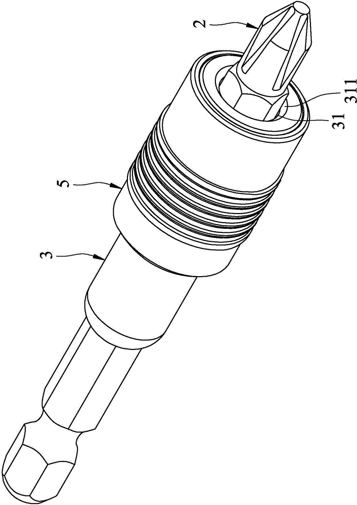
[0027] Such as image 3 and Figure 4 As shown, the embodiment of the quick release socket tool of the present invention can be used to install and remove a subhead 2 and includes a rod body 3, a linkage device 4, and a fastening device 5.

[0028] The rod body 3 includes a slot 31 arranged in the axial direction and having a port 311, a buckling hole 32 adjacent to the port 311, a long groove hole 33 away from the port 311, and a slot adjacent to the port 311 and extending along The front edge 34 of the rod body 3 extends radially outward.

[0029] In this embodiment, the slot 31 further has a slot section 312 adjacent to the port 311 and capable of inserting the screwdriver head 2, and a guide groove section 313 far away from the port 311. The cross-sectional shape of the slot segment 312 corresponds to the shape of the driver head 2, and preferably is a regular polygon...


PUM


Abstract

The invention discloses a rapid-releasing sleeving tool allowing a screwdriver bit to be installed and uninstalled. The rapid-releasing sleeving tool comprises a rod body, a linkage device and a buckling device. The rod body comprises a groove hole provided with an end opening, a buckling hole penetrating outwards from the groove hole and a long trough hole far away from the end opening. The linkage device comprises a guide pin arranged in the long trough hole in a penetrating mode and a first elastic member which can abut against the guide pin and is close to the end opening. The buckling device comprises a bundling ring arranged outside the rod body in a sleeving mode and provided with an inner ring groove, a second elastic member capable of making the bundling ring abut against the guide pin and a positioning ball contained in the buckling hole. The buckling device can move between a buckling position and a releasing position. When the buckling device is in the buckling position, the screwdriver bit is buckled by the positioning ball to be fixed in the groove hole. When the buckling device is in the releasing position, the screwdriver bit can slide axially along the rod body to be released. According to the structure, the rapid-releasing sleeving tool can slide smoothly and a good positioning property is achieved.

Description

technical field [0001] The invention relates to a socket tool, in particular to a quick-release socket tool. Background technique [0002] Such as figure 1 As shown, the existing socketing device for installing and removing the head 10 includes a rod body 11 including a slot 111 and an opening 112, a tie ring 12 sleeved outside the rod body 11, a container The sliding member 13 placed in the slot 111 , a spring 14 against the sliding member 13 , a positioning bead 15 corresponding to the bit 10 , and a fastening bead 16 corresponding to the sliding member 13 . [0003] When the operator wants to pull out the screwdriver bit 10, the clamp ring 12 needs to be pushed out along the axial direction of the rod body 11, and the positioning bead 15 and the fastening bead 16 can be kept away from the screwdriver bit 10 and the screwdriver bit 10 respectively. Slider 13, now just can push against this slider 13 by the elastic force of this spring 14, and this screwdriver bit 10 is d...

Claims


Application Information

Patent Timeline
IPC IPC(8): B25B23/00B25G3/02
Inventor 陈昶勋陈怡儒
Owner 叶淑惠
Why Eureka
Try Eureka