Supercharge Your Innovation With Domain-Expert AI Agents!

Bridge with bracket tension and compression transfer beam and construction method of bridge

A construction method and a technology of compression conversion, which is applied to bridges equipped with support tension-compression conversion beams and their construction fields, which can solve the problems of high price, small tension, and easy damage, so as to enhance the tensile bearing capacity and reduce construction costs , cheap effect

Active Publication Date: 2016-03-30
CHINA RAILWAY MAJOR BRIDGE ENG GRP CO LTD
View PDF6 Cites 0 Cited by
  • Summary
  • Abstract
  • Description
  • Claims
  • Application Information

AI Technical Summary

Problems solved by technology

However, the tensile force that can be transmitted by traditional tension and compression bearings is relatively small, generally about 20% of the compressive bearing capacity, and it is easily damaged under repeated tension and compression loads, which seriously affects the service life of the bearing, and its price is very expensive. It is not conducive to reducing construction costs and maintenance and repair costs during the bridge operation phase
[0003] In order to solve the above problems and prolong the service life of the bearing, in addition to improving the performance of the tension and compression bearing itself, there is currently a lack of a means to use the structure of the bridge itself to solve the tensile capacity of the tension and compression bearing

Method used


Image

  • Bridge with bracket tension and compression transfer beam and construction method of bridge
  • Bridge with bracket tension and compression transfer beam and construction method of bridge
  • Bridge with bracket tension and compression transfer beam and construction method of bridge

Examples


Embodiment Construction

[0026] The present invention will be described in further detail below in conjunction with the accompanying drawings.

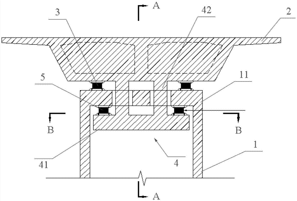
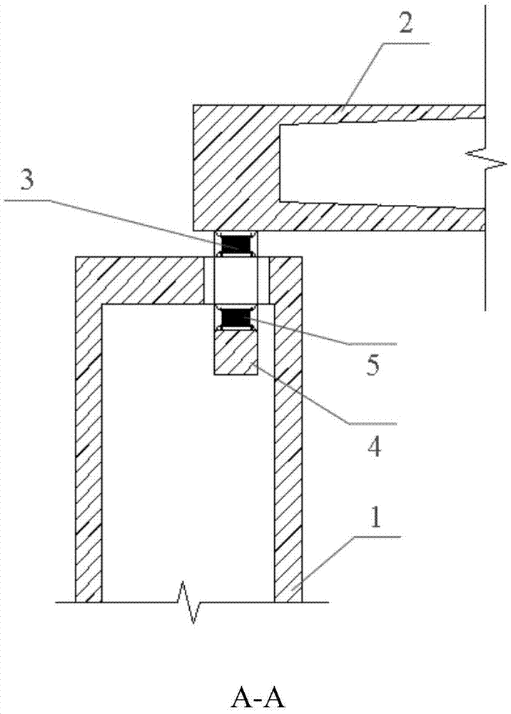
[0027] see figure 1 As shown, the present invention provides a bridge with support tension-compression conversion beams, which includes a plurality of hollow thin-walled piers 1, a main beam 2, an upper support 3, a support tension-compression conversion beam 4 and a lower support 5 .

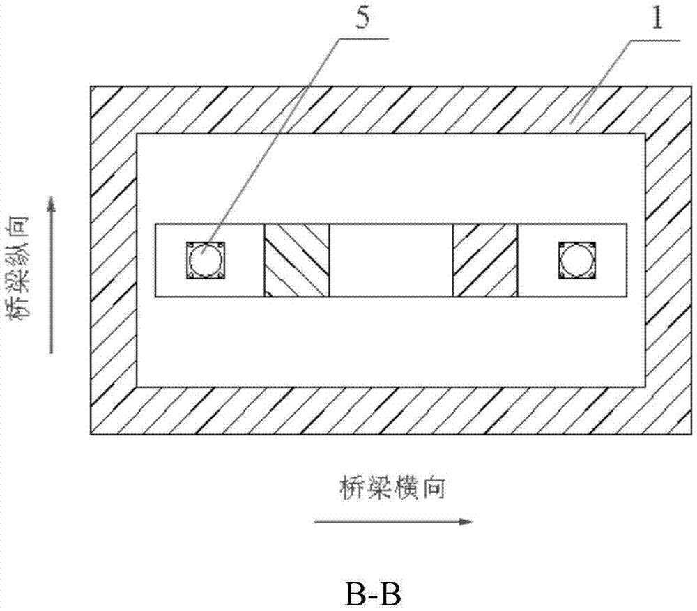
[0028] The number of hollow thin-walled piers 1 can be reasonably determined according to the span of the bridge. There is a roof 11 on it, the main beam 2 is arranged on the roof 11, and a row of upper supports 3 is arranged between the bottom of the main beam 2 and the roof 11. There are two upper supports 3 in the invention, which are arranged symmetrically along the transverse direction of the bridge, and are used to support the main girder 2 .

[0029] The support tension-compression conversion beam 4 includes a beam 41 and a vertical beam 42 , wherein the beam 41 is em...


PUM


Abstract

The invention discloses a bridge with a bracket tension and compression transfer beam and a construction method of the bridge, and relates to the field of bridge design. The bridge comprises a hollow thin wall pier, wherein the hollow thin wall pier comprises a top plate with an opening, a main beam arranged on the top plate, at least two upper brackets, a bracket tension and compression transfer beam, and at least two lower brackets; at least one upper bracket is arranged on one side of the center line of the bridge, at least one upper bracket is arranged on the other side of the center line of the bridge, the upper brackets are positioned between the top plate and the bottom of the main beam, and two ends of the each of the upper brackets are respectively connected with the top plate and the main beam; the bracket tension and compression transfer beam comprises a crossbeam which is embedded into the hollow thin wall pier and is connected with the bottom of the main beam; at least one lower bracket is arranged on one side of the bridge, at least one lower bracket is arranged on the other side of the center line of the bridge, the lower bracket is positioned between the top plate and the crossbeam, and two ends of each of the lower brackets are respectively connected with the top plate and the crossbeam. According to the bridge disclosed by the invention, the brackets are always in the pressed state, so that the tensile carrying capacity is effectively strengthened, and the construction cost is low.

Description

technical field [0001] The invention relates to the field of bridge design, in particular to a bridge provided with a bearing tension-compression conversion beam and a construction method thereof. Background technique [0002] Bridge bearings are important force-transmitting devices of bridges, and tension-compression bearings are widely used in bridge structures at present. In actual engineering, the traditional method is to set spherical tension-compression bearings on the top of the bridge piers, and the main girder transmits the tension or pressure to the bridge piers through the spherical tension-compression bearings. However, the tensile force that can be transmitted by traditional tension and compression bearings is relatively small, generally about 20% of the compressive bearing capacity, and it is easily damaged under repeated tension and compression loads, which seriously affects the service life of the bearings, and its price is very expensive. It is not conduciv...

Claims


Application Information

Patent Timeline
IPC IPC(8): E01D1/00E01D19/02E01D19/04E01D21/00
CPCE01D1/00E01D19/02E01D19/041E01D21/00
Inventor 余祥亮徐伦王伟臣潘东发林晚兰吴方明涂满明毛伟琦
Owner CHINA RAILWAY MAJOR BRIDGE ENG GRP CO LTD
Features
  • R&D
  • Intellectual Property
  • Life Sciences
  • Materials
  • Tech Scout
  • Unparalleled Data Quality
  • Higher Quality Content
  • 60% Fewer Hallucinations
Learn More