Piling mechanism of piling machine and piling machine

A technology of pile driver and transmission mechanism, which is applied in the direction of sheet pile wall, foundation structure engineering, building type, etc. It can solve the problems of poor reliability of striking force and achieve the effect of high striking force and good reliability

Active Publication Date: 2016-03-30
ZHEJIANG JIAHONG TOOL MFG CO LTD
View PDF5 Cites 8 Cited by
  • Summary
  • Abstract
  • Description
  • Claims
  • Application Information

AI Technical Summary

Problems solved by technology

It solves the problem of poor striking force and reliability of the existing pile driver

Method used


Image

  • Piling mechanism of piling machine and piling machine
  • Piling mechanism of piling machine and piling machine
  • Piling mechanism of piling machine and piling machine

Examples


Embodiment Construction

[0038] Below in conjunction with each accompanying drawing, the present invention is described in detail.

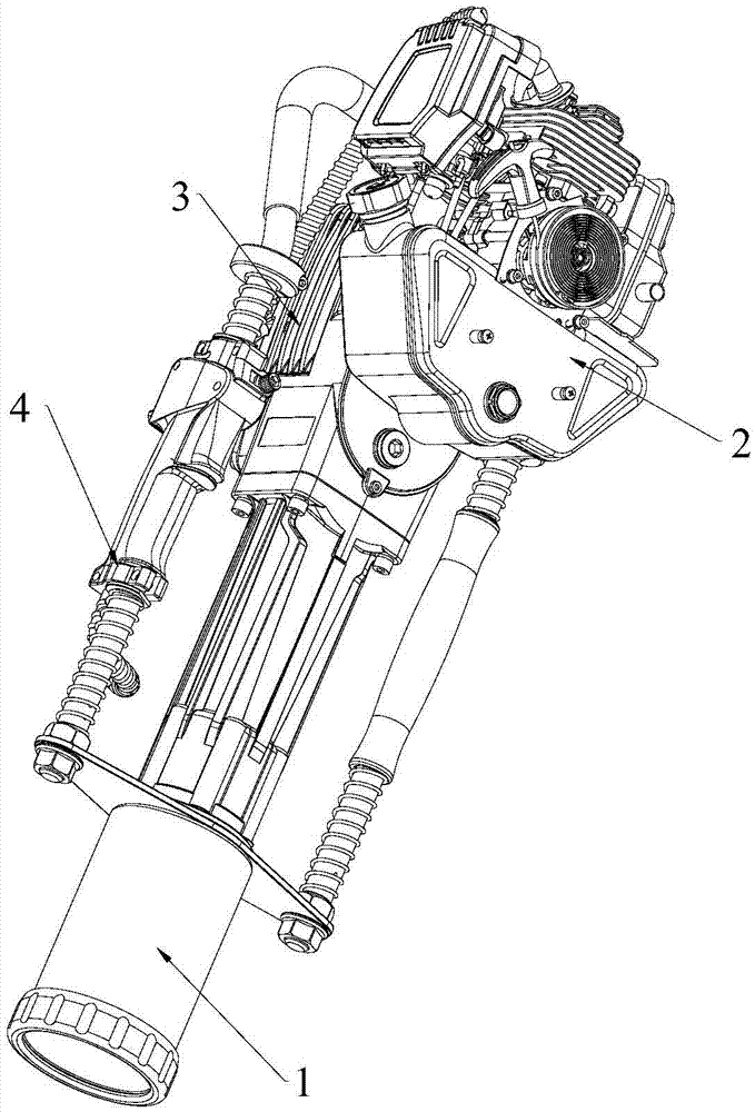
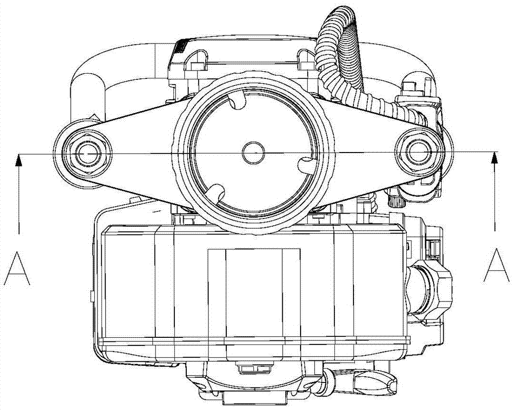
[0039] Such as Figure 1~4 As shown, a pile driver includes a gasoline engine 2, a transmission mechanism 3 and a piling mechanism 1. The gasoline engine 2 is used to drive the transmission mechanism 3 to work, and the transmission mechanism 3 cooperates with the piling mechanism 1 to drive the piling mechanism to work.

[0040] In this embodiment, the pile driver also includes a damping mechanism 4 that cooperates with the pile driver.

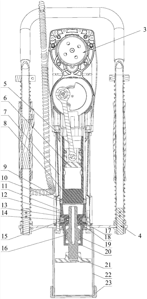
[0041] Such as image 3 with 4 Shown, the piling mechanism of the present embodiment comprises:

[0042] Cylinder 7;

[0043] The impact cylinder 8 is slidingly arranged in the cylinder body 7, one end of the impact cylinder is closed, and the other end is open;

[0044] The impact piston 6 is slidingly arranged in the impact cylinder, and the impact piston is linked with the transmission mechanism 3 through the connecting rod 5; ...


PUM


Abstract

The invention discloses a piling mechanism of a piling machine. The piling mechanism of the piling machine comprises a barrel, an impact cylinder, an impact piston, an impactor guide sleeve, a wood pile guide sleeve, an impactor and an inner pile head; the impact cylinder is arranged in the barrel in a sliding mode, one end of the impact cylinder is closed, and other end of the impact cylinder is opened; the impact piston is arranged in the impact cylinder in a sliding mode and linked with a transmission mechanism; the wood pile guide sleeve is fixed relative to the barrel, the impactor is installed on the impactor guide sleeve in a sliding mode, one end of the impactor penetrates out of the impactor guide sleeve and extends to the impact cylinder, and other other end of the impactor penetrates out of the impactor guide sleeve and is located in the wood pile guide sleeve; the inner pile head is fixed relative to the end, located in the wood pile guide sleeve, of the impactor. According to the piling mechanism of the piling machine, one end of the impact cylinder is opened, the other end of the impact cylinder is closed, the impactor is impacted through the impact cylinder arranged in the barrel in a sliding mode, and only the portion, between the impact piston and the inner side wall of the impact cylinder, in the impact cylinder needs to be sealed; compared with an exiting structure, the reliability is good, and the strike force is larger.

Description

technical field [0001] The invention relates to engineering equipment, in particular to a pile driving mechanism of a pile driver and the pile driver. Background technique [0002] In landscaping, in order to protect the trees, flowers, etc., it is usually necessary to set up guardrails, which need to be driven into the soil to achieve a certain strength. In the prior art, piling is usually carried out manually, which has low work efficiency and consumes physical strength, and the depth of the guardrail implantation cannot be guaranteed. In the prior art, pile drivers are also used to drive piles, but the existing pile drivers are usually heavy and require two or more people to operate normally. In addition, this pile driver requires an independent air source. It is inconvenient to install and carry the air source. [0003] There is a pile driver in the prior art, which includes a gasoline engine, a transmission mechanism, an impact cylinder, an impact piston and a hammer....

Claims


Application Information

Patent Timeline
Patent Type & Authority Applications(China)
IPC IPC(8): E02D7/12E02D7/14E04H12/22
CPCE02D7/12E02D7/14E04H12/22
Inventor 章磊徐武民
Owner ZHEJIANG JIAHONG TOOL MFG CO LTD
Why Eureka
Try Eureka