
Power-grid telegraph-pole erecting self-loading-unloading device and construction method thereof

A utility pole, self-loading and unloading technology, applied in the direction of hoisting device, building type, building, etc., can solve the problems of not being able to use utility poles alone, complicated operation, prone to accidents, etc., and achieve the effect of saving manpower, convenient use and stable walking.

Inactive Publication Date: 2016-03-30
江苏东方宏达电力发展有限公司
View PDF7 Cites 35 Cited by
  • Summary
  • Abstract
  • Description
  • Claims
  • Application Information

AI Technical Summary

Problems solved by technology

[0005] At present, electric poles play a very important role in power transmission, which makes erecting electric poles essential. The patent application number 201410297193.1 discloses a cement electric pole erecting vehicle. This design can achieve the purpose of erecting electric poles. However, the poles must be placed on the device from the ground with the help of additional mechanisms or devices. It is relatively cumbersome to operate in the field and cannot be used alone to realize the erection of poles. The cost is relatively high, and the mechanism only has two Wheels, unstable during walking, prone to accidents

Method used


Image

  • Power-grid telegraph-pole erecting self-loading-unloading device and construction method thereof
  • Power-grid telegraph-pole erecting self-loading-unloading device and construction method thereof
  • Power-grid telegraph-pole erecting self-loading-unloading device and construction method thereof

Examples


Embodiment Construction

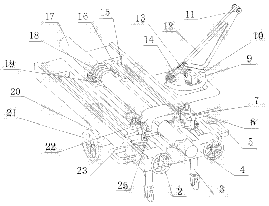
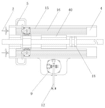
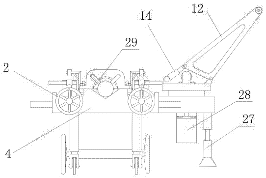
[0029] As shown in the figure, the self-loading and unloading device is erected on the power grid pole, including a vehicle frame 4, a support 20 is installed under the vehicle frame 4, wheels 21 are installed on the support 20, and a universal wheel 3 is installed at the front end of the vehicle frame 4; Screw rods 16 are installed on both sides of the vehicle frame 4, and the slider 25 that slides back and forth on the screw rod 16 through the screw handle 2 is installed on the screw rod 16. Rod 15. Vehicle frame 4 both sides are equipped with handlebar 5, construction personnel can pull the handle to control the traveling direction of vehicle.

[0030] One end in the middle of the vehicle frame 4 is equipped with a fixed fastening frame upper cover 18 and a fixed fastening frame lower cover 19 assembled jacket one, the two sides of the jacket one are provided with a rotating shaft inserted in the vehicle frame 4; The other end in the middle of the vehicle frame 4 is provid...


PUM


Abstract

The invention discloses a power-grid telegraph-pole erecting self-loading-unloading device. The power-grid telegraph-pole erecting self-loading-unloading device comprises a vehicle frame. A support is installed below the vehicle frame. Wheels are installed on the support, and universal wheels are installed at the front end of the vehicle frame. The power-grid telegraph-pole erecting self-loading-unloading device is characterized in that lead screws are installed on the two sides of the vehicle frame, and sliding blocks controlled through lead screw hand wheels to slide on the lead screws back and forth are installed on the lead screws; a first clamping sleeve formed by assembling a fixing-fastening-frame upper cover and a fixing-fastening-frame lower cover is installed at one end of the middle of the vehicle frame, and rotating shafts are arranged on the two sides of the first clamping sleeve and inserted into the vehicle frame. The power-grid telegraph-pole erecting self-loading-unloading device and a construction method of the power-grid telegraph-pole erecting self-loading-unloading device have the advantages that when a telegraph pole is erected, use is convenient, labor is saved, walking is stable, the construction speed is high, and meanwhile the power-grid telegraph-pole erecting self-loading-unloading device and the construction method are suitable for a flat-road region with sufficient power in a construction region and a remote mountain road rough region, high in practicability and suitable for use and popularization.

Description

technical field [0001] The invention relates to a power grid construction device, in particular to a self-loading and unloading device for erecting power grid utility poles and a construction method thereof, belonging to the technical field of power construction. Background technique [0002] Electric power engineering refers to engineering related to the production, transmission, and distribution of electric energy. In a broad sense, it also includes engineering that uses electricity as power and energy in various fields. The bubbling area is composed of angle steels juxtaposed with each other, and the arrangement direction of the angle steels is parallel to the direction of liquid flow. [0003] For example, an application number of CN104088501A discloses a cement utility pole stringing vehicle, which includes a vehicle frame and a utility pole lifting device and a utility pole support device arranged on the vehicle frame; the front end of the vehicle frame is provided wit...

Claims


Application Information

Patent Timeline
IPC IPC(8): E04H12/34
CPCB66F11/00E04H12/34E04H12/347
Inventor 陈庆熊达煜
Owner 江苏东方宏达电力发展有限公司
Learn More