Refrigeration device

A refrigeration device and liquid refrigerant technology, applied in refrigerators, refrigeration components, refrigeration and liquefaction, etc., can solve the problems of reducing system capacity and energy efficiency, improve capacity and energy efficiency, increase suction specific volume, and solve system energy efficiency reduction Effect

Inactive Publication Date: 2016-03-30
YORK GUANGZHOU AIR CONDITIONING & REFRIGERATION +1
View PDF7 Cites 11 Cited by
  • Summary
  • Abstract
  • Description
  • Claims
  • Application Information

AI Technical Summary

Problems solved by technology

[0005] In short, no matter whether it is a refrigeration device that adopts the suction dryness control method or the intermediate pres

Method used


Image

  • Refrigeration device
  • Refrigeration device
  • Refrigeration device

Examples


Example Embodiment

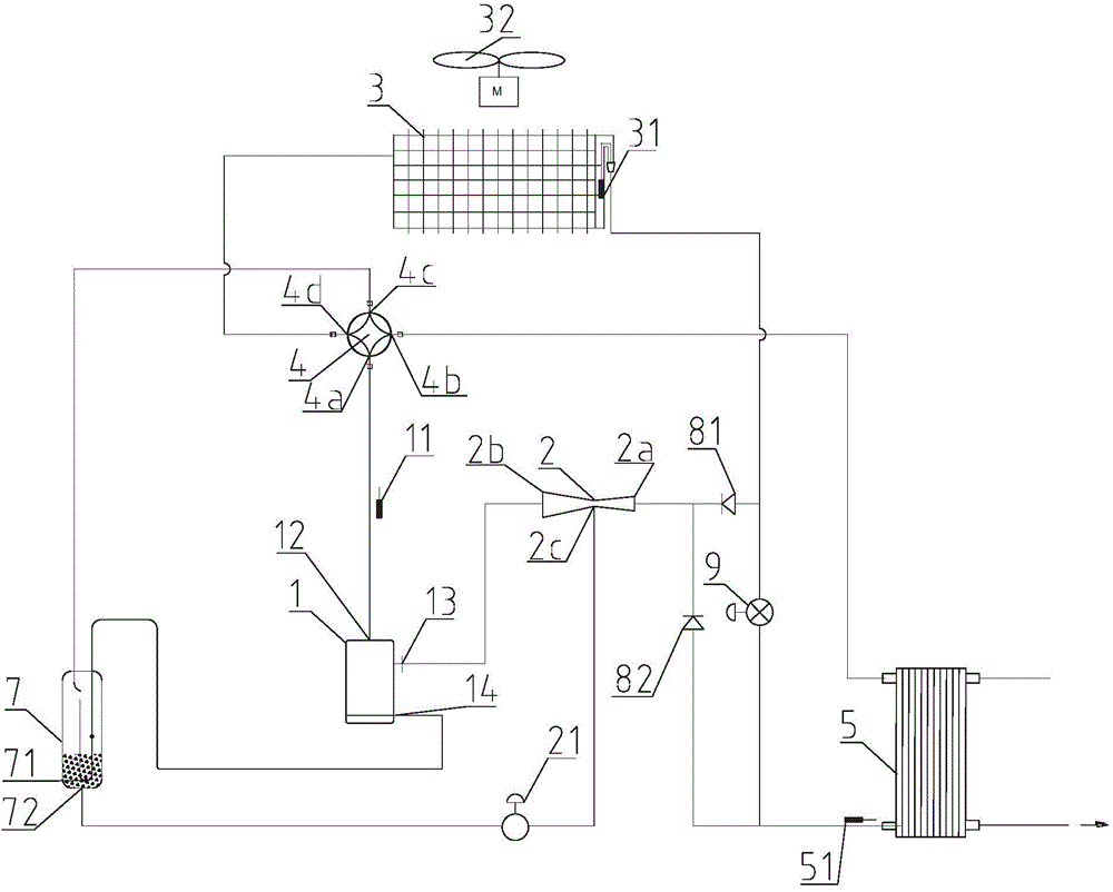
[0032] Preferably, as figure 1 In the shown first embodiment of the present invention, the refrigeration device with ejector is EVI ejector economizer heat pump system, and the gas-liquid separation equipment is gas-liquid separator 7, which is set at the bottom of gas-liquid separator 7 There is a bottom port 72 , and the low-pressure port 2c of the ejector 2 is connected to the bottom port 72 of the gas-liquid separator 7 via the solenoid valve 21 . In the illustrated embodiment, a compressor 1 , an air source heat exchanger 3 , a user side heat exchanger 5 , a gas-liquid separator 7 , an ejector 2 and an expansion valve 9 are included. A first temperature sensor 11 is provided on the air outlet pipeline of the compressor 1 ; a second temperature sensor 31 and a fan 32 are provided on the air source heat exchanger 3 . The solenoid valve 21 is provided between the low-pressure port 2c and the bottom port 72 . The solenoid valve 21 is used to control the switch of the ejecto...


PUM


Abstract

The invention discloses a refrigeration device comprising the following structures: a compressor; an air source heat exchanger; a user side heat exchanger with a liquid refrigerant port connected with that of the air source heat exchanger, and a throttling gear is arranged between the liquid refrigerant ports of the user side heat exchanger and the air source heat exchanger; a gas-liquid separator used for separating gas from liquid; an ejector with a high pressure port, an ejection outlet, and a low pressure port, wherein the high pressure port is used for receiving high pressure liquid refrigerant or high pressure gas refrigerant, the ejection outlet is connected with the compressor, the low pressure port is connected with the gas-liquid separator, and a solenoid is arranged between the low pressure port and a bottom port. The refrigeration device can effectively solve the system energy efficiency reduction problems caused by controlling exhaust temperature, and can eliminate an exhaust temperature control blind zone.

Description

technical field [0001] The invention relates to the refrigeration field, in particular to a refrigeration device. Background technique [0002] Refrigerants are used in refrigeration applications to avoid excessive compressor discharge temperatures. The exhaust temperature of refrigerants such as R32 after compression is higher than that of refrigerants such as R22, R407C and R410A. Under the working conditions of some refrigeration equipment, it even exceeds the high temperature resistance range of ordinary compressors. Theoretically, this problem can be solved from two aspects: one is to improve the high temperature resistance of the compressor itself; the other is to improve the refrigeration system. So far, there has been no substantial progress in improving the high temperature resistance of the compressor itself. In terms of improving the refrigeration system, there have been many methods to solve the problem of high exhaust temperature of the R32 system, including t...

Claims


Application Information

Patent Timeline
IPC IPC(8): F25B13/00F25B41/00F25B41/40
Inventor 王林忠苏秀平
Owner YORK GUANGZHOU AIR CONDITIONING & REFRIGERATION
Why Eureka
Try Eureka