Solution spray type heat pump set

A technology of heat pump unit and solution pump, which is applied in the direction of heating and cooling combination, refrigerator, compressor, etc., which can solve the problems of freezing of circulating water, inability to realize heating, and low energy efficiency of cooling, so as to reduce metal materials and avoid removal Frost problem, the effect of large heat transfer coefficient

Inactive Publication Date: 2011-07-06
TSINGHUA UNIV
View PDF0 Cites 19 Cited by
  • Summary
  • Abstract
  • Description
  • Claims
  • Application Information

AI Technical Summary

Problems solved by technology

[0003] like figure 1 The shown air source heat pump unit is currently a common cold and heat source solution for central air conditioning. However, when the air source heat pump unit is in cooling operation in summer, the energy efficiency ratio COPc of the unit is much lower than that of the water-cooled chiller unit. Under the condition that the source heat pump has a local heat island effect, the cooling energy efficiency of the air source heat pump unit is lower than that of COPc; in winter heating, due to the problem of frost on the surface of the evaporator, the frost on the surface of the evaporator reduces the energy efficiency ratio of the air source heat pump to COPh , the defrosting operation will lead to intermittent heating, affecting the comfort of the indoor environment, and reducing the safety and stability of the unit
In addition, the air source heat exchanger has a low heat transfer coefficient, large volume, and many consumables, which not only increases the initial investment of the equipment, but also puts forward higher requirements on the operating conditions such as the placement space of the unit, which limits the use of the air source heat pump unit
[0004] In order to improve the energy efficiency ratio (COPc) of the air source heat pump unit during cooling operation in summer, it has been proposed as follows: figure 2 In the scheme of evaporative cooling unit shown in the figure, during cooling in summer, the cooling energy efficiency ratio COPc of the unit is greatly improved by spraying circulating water to reduce the condensation temperature of the refrigeration cycle; Heating function in winter, since the circulating water is used to spray the air and get heat from the air in winter, when the heating operation is under low ambient temperature, the circulating water will inevitably freeze, and the heating cannot be realized

Method used


Image

  • Solution spray type heat pump set
  • Solution spray type heat pump set
  • Solution spray type heat pump set

Examples


Embodiment 1

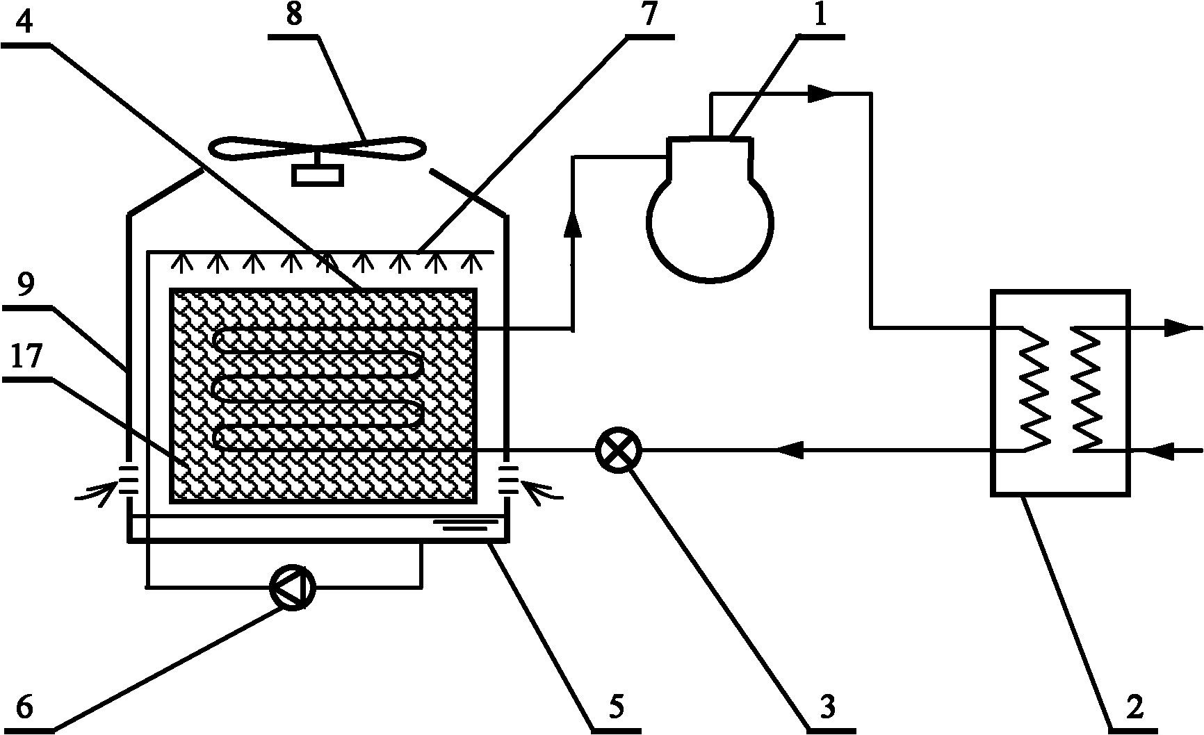
[0033] Figure 4 It is the structural principle diagram of the first embodiment of the solution spray type air conditioner heat pump unit provided by the present invention. In this embodiment, the recooling and heat of the high-pressure liquid refrigerant is used as the regeneration heat source of the solution, and it includes a compressor 1, a first heat exchanger Device 2, throttling device 3, second heat exchanger 4, solution collecting pan 5 located at the lower part of the second heat exchanger, first solution pump 6a, heat exchanger sprayer 7, fan 8 and heat exchanger shell 9. An air inlet is provided at the middle and lower part of the heat exchanger shell 9, and the outdoor air flows through the second heat exchanger 4 and flows out of the heat exchanger shell 9 under the action of the fan 8. It is characterized in that: the solution spray type heat pump unit is also It includes a four-way valve 10 and a solution-refrigerant heat exchanger 11; the solution-refrigerant ...

Embodiment 2

[0038] Figure 5 It is the structural principle diagram of the second embodiment of the solution spray type air-conditioning heat pump unit provided by the present invention. This embodiment uses the recooling and heat of the high-pressure liquid refrigerant as the regeneration heat source of the solution. Compared with the first embodiment, the difference lies in: On the vapor compression heat pump circuit, a communication pipe is added between the outlet of the refrigerant side of the first heat exchanger 2 and the inlet of the throttling device 3, and the first valve 12 is arranged on the communication pipe; at the same time, the solution- A second valve 13 is set on the refrigerant side inlet pipeline of the refrigerant heat exchanger 11; a solution regenerator 16 is set above the second heat exchanger 4 inside the heat exchanger shell 9, and a porous filler 17 is set in the solution regenerator 16 The heat exchanger shower 7 is made up of the first regenerator-heat exchan...

Embodiment 3

[0044] Figure 6 It is the structural principle diagram of the third embodiment of the solution spray type air conditioner heat pump unit provided by the present invention. In this embodiment, the recooling and heat of the high-pressure liquid refrigerant is used as the regeneration heat source of the solution, and it includes a compressor 1, a first heat exchanger Device 2, throttling device 3, second heat exchanger 4, solution collecting pan 5 located at the lower part of the second heat exchanger, first solution pump 6a, heat exchanger sprayer 7, fan 8 and heat exchanger shell 9. An air inlet is provided at the middle and lower part of the heat exchanger shell 9, and the outdoor air flows through the second heat exchanger 4 and flows out of the heat exchanger shell 9 under the action of the fan 8. It is characterized in that: the solution spray type heat pump unit is also Including a four-way valve 10 and a solution-refrigerant heat exchanger 11, the solution-refrigerant he...


PUM


Abstract

The invention relates to a solution spray type heat pump set, belonging to the field of refrigerating and air conditioning equipment. The solution spray type heat pump set has the technical characteristics that the set radiates condensed heat to the environment in summer and takes heat from the outdoor air environment in winter by using solution spray, and the solution is regenerated by using heat released by recooling a high-pressure liquid refrigerant. Compared with an air source heat pump unit, the solution spray type heat pump set has the obvious characteristics of compact set structure, low initial equipment investment, high energy efficiency ratio for refrigeration operation in summer, no need of defrosting in winter, efficient, continuous and stable refrigeration operation and the like.

Description

technical field [0001] The invention relates to a solution spraying type heat pump unit, which uses solution spraying to realize that the unit emits condensation heat to the environment in summer, and obtains heat from the outdoor air environment in winter, and is beneficial to the recooling and heating of high-pressure liquid refrigerant to regenerate the solution, belonging to In the field of refrigeration and air conditioning equipment, it is especially suitable for use in areas with low external temperature in winter. Background technique [0002] With the rapid development of social economy and the improvement of people's living standards, people's pursuit of quality of life is increasing. The energy consumption of building air-conditioning occupies a large share in the total energy consumption. According to statistics, the annual power consumption of central air-conditioning is about It accounts for about 60% of the total electricity consumption of buildings. Therefor...

Claims


Application Information

Patent Timeline
Patent Type & Authority Applications(China)
IPC IPC(8): F25B13/00F25B29/00F25B41/04F25B41/06F24F5/00F24F13/30
Inventor 石文星董俐言王宝龙李先庭韩林俊李筱吴伟李丹阳
Owner TSINGHUA UNIV
Why Eureka
Try Eureka