
Condensing gas boiler

A gas-fired boiler, condensing technology, applied in the field of gas-fired boilers and condensing gas-fired boilers, can solve the problems of hindering heat exchange, large area, burner extinguishing, etc., to ensure heat exchange efficiency, small footprint, sufficient heat transfer effect

Inactive Publication Date: 2010-07-21
A O SMITH CHINA WATER HEATER CO LTD
View PDF6 Cites 17 Cited by
  • Summary
  • Abstract
  • Description
  • Claims
  • Application Information

AI Technical Summary

Problems solved by technology

Such products generally have the following disadvantages: 1) There is only one-stage heat exchange, and the heat exchange is insufficient; 2) When condensed water is generated, the burner is easily extinguished; the condensed water cannot be discharged, and it is easy to form a water film on the surface of the copper tube, hindering the exchange heat; 3) requires a large number of copper pipes and a larger footprint

Method used


Image

  • Condensing gas boiler
  • Condensing gas boiler
  • Condensing gas boiler

Examples


Embodiment 1

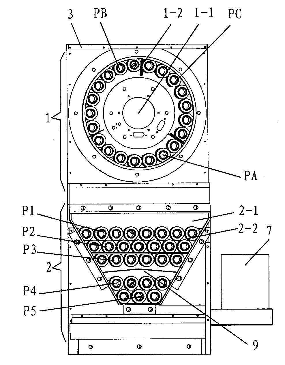
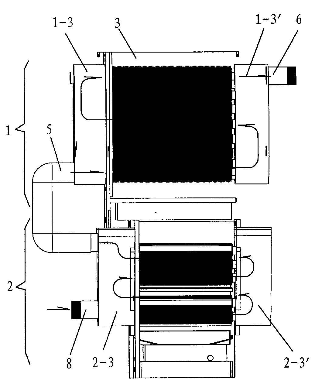
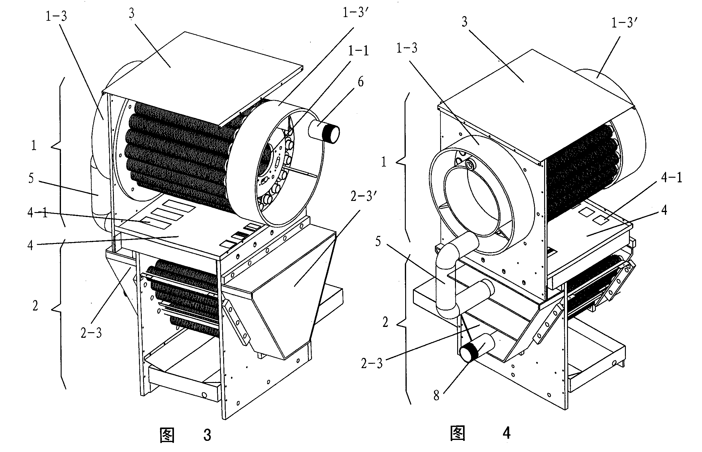
[0016] The condensing gas boiler of this preferred embodiment is as Figure 1 to Figure 4 As shown, it is mainly composed of a burner (not shown in the figure) and a heat exchange device with flue gas and water flow channels. The heat exchange device includes an upper annular horizontal heat exchanger 1 and a lower V-shaped heat exchanger 2 located in the casing 3 and connected in series. The circumference of the annular horizontal heat exchanger 1 is distributed with a first group of water pipes forming a roundabout flow channel, and the middle part is a cylindrical combustion chamber 1-1. A burner is installed at the front end of the cylindrical combustion chamber 1-1, and the V-shaped flue gas flow channel 2 of the V-shaped heat exchanger 2 passes through the exhaust holes 4-1 facing downwards at both ends of the mesh plate 4 separating the two heat exchangers. -1 connectivity.

[0017] The V-shaped flue gas flow channel 2-1 is equipped with a second group of water pipes ...

Embodiment 2

[0026] The condensing gas boiler of the present embodiment is as Figure 5 , Figure 6 As shown, the difference from Embodiment 1 is that the horizontal heat exchanger is located on one side of the V-shaped heat exchanger, and communicates with each other through a series of flues; its working principle and main advantages are the same as Embodiment 1 , without further details.


PUM


Abstract

The invention relates to a condensing gas boiler, which belongs to the technical field of heat exchange facilities. The condensing gas boiler mainly comprises a burner and a heat exchange device with smoke and water passages, wherein the heat exchange device comprises a horizontal heat exchanger and a V-shaped heat exchanger which are mutually connected in series; a first group of water pipes forming a roundabout flow passage are distributed at the circumference of the horizontal heat exchanger, and the middle part of the horizontal heat exchanger is provided with a cylindrical combustion chamber; the burner is arranged at one end of the cylindrical combustion chamber, and the smoke passes through the horizontal heat exchanger and enters the V-shaped smoke passage of the V-shaped heat exchanger through a downward through hole; a second group of water pipes forming a roundabout flow passage are distributed in the V-shaped smoke passage at intervals; and reverse heat exchange is formed between the water first flowing through the second group of water pipes and then the first group of water pipes and the smoke coming from the combustion chamber and flowing through the V-shaped smoke passage. The heat exchange is sufficient, the flow rate of the cooled smoke can be kept to ensure the heat exchange efficiency, and the condensing gas boiler has a reasonable structure and occupies small area.

Description

technical field [0001] The invention relates to a gas boiler, in particular to a condensing gas boiler, which belongs to the technical field of heat exchange facilities. Background technique [0002] According to the applicant's understanding, the typical structure of the existing condensing heat exchanger for gas water heaters is disclosed in the Chinese invention patent with the application number 200820052420.4 and the application date of 2008-03-04. Smoke port, smoke exhaust port, cold water inlet, hot water outlet, and condensed water outlet in the heat exchange chamber. The heat exchange chamber is composed of a heat exchanger shell and a heat exchanger inner cylinder to form a channel with a circular cross section. , the inner tube of the heat exchanger and the outer shell of the heat exchanger are respectively connected with the smoke inlet and the smoke exhaust port. The heat exchange tubes are arranged in the heat exchange chamber in the form of spiral tubes. The ...

Claims


Application Information

Patent Timeline
Patent Type & Authority Applications(China)
IPC IPC(8): F24H1/40F28F19/00
Inventor 潘晓春马鸿飞汤成杰曾梓奡曹磊
Owner A O SMITH CHINA WATER HEATER CO LTD
Learn More