
Helicopter lift speed fusion algorithm

A technology of lift speed and fusion algorithm, applied in computing, instruments, geometric CAD, etc., can solve problems such as helicopter lift speed fluctuations, improve flight quality, and be beneficial to flight control.

Active Publication Date: 2019-10-11
TAIYUAN AERO INSTR
View PDF5 Cites 0 Cited by
  • Summary
  • Abstract
  • Description
  • Claims
  • Application Information

AI Technical Summary

Problems solved by technology

What the present invention is to solve is the problem between the fluctuation and delay of the helicopter's lifting speed, so as to achieve the purpose of reducing the fluctuation and the delay characteristic at the same time

Method used


Image

  • Helicopter lift speed fusion algorithm
  • Helicopter lift speed fusion algorithm
  • Helicopter lift speed fusion algorithm

Examples


Embodiment

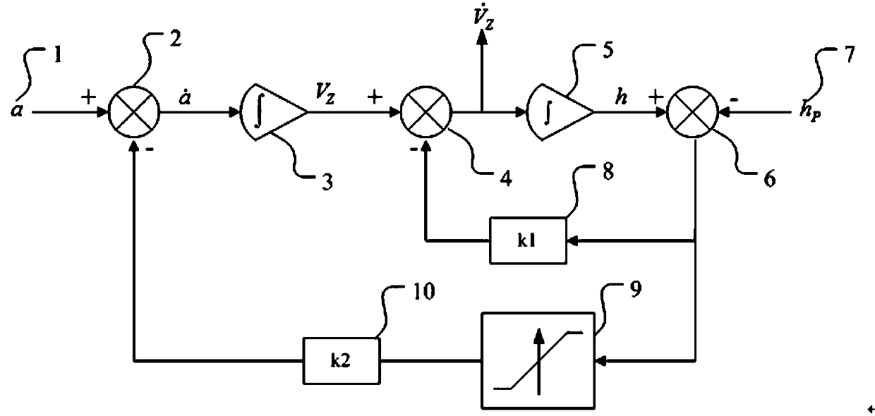
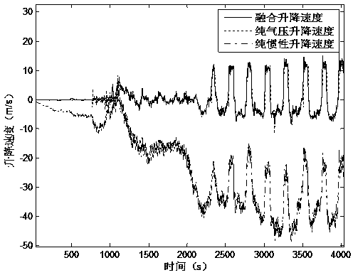
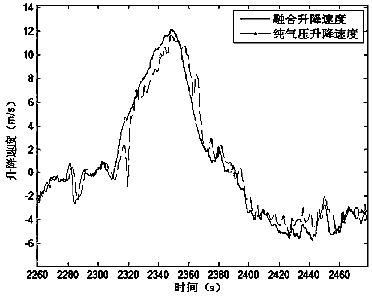
[0027] Example: A certain type of helicopter uses the vertical acceleration measured by the inertial sensor and the barometric altitude measured by the atmospheric sensor to perform fusion calculation according to formula (1) to formula (4) to obtain the fusion lifting speed see figure 1 and figure 2 Integrating the ascending and descending speed in the middle, the ascending and descending speed is calculated by applying the existing pressure-altitude difference, see figure 1 and figure 2 For the pure air pressure ascending and descending velocity in , the ascending and descending velocity calculated by applying the integral of the vertical acceleration measured by the inertial sensor is shown in figure 1 The pure inertial lifting speed in . Depend on figure 1 It can be seen that the magnitude of the fusion lifting velocity is consistent with the pure air pressure lifting velocity, but the pure inertial lifting velocity gradually diverges with time, as shown by figure 2...


PUM


Abstract

The invention belongs to the field of helicopter atmospheric systems, particularly relates to a helicopter take-off and landing speed fusion algorithm, and aims to solve the problems of take-off and landing speed fluctuation and time delay of a helicopter and fulfill the aim of lowering a time delay characteristic while reducing fluctuation. The helicopter take-off and landing speed fusion algorithm is a second-order integral operation algorithm with negative feedback control; an inertial vertical acceleration is taken as an input quantity of integral operation; and an atmospheric pressure height is taken as an observed quantity of the negative feedback control. The helicopter take-off and landing speed fusion algorithm has a long-term stability characteristic in the prior art, but is remarkably superior to the prior art in fluctuation and time delay characteristics, is beneficial to flight control, and contributes to enhancing the flight quality.

Description

technical field [0001] The invention belongs to the field of helicopter atmospheric systems, and in particular relates to a fusion algorithm of helicopter ascending and descending speeds. Background technique [0002] The vertical speed is an important parameter for the pilot to control the aircraft and the vertical direction control of the flight controller. It is usually obtained by differential calculation from the air pressure altitude measured by the static pressure sensor located at the fuselage position. The helicopter takes off by rotating the rotor to form a downwash to generate thrust to overcome the weight of the body. Since the entire fuselage is in the package of the downwash of the rotor, it is difficult to find a suitable installation position for the static pressure sensor that is not affected by the rotor. To accurately measure the real static pressure, although the helicopter has corrected the error of the static pressure source, due to the complexity of th...

Claims


Application Information

Patent Timeline
Patent Type & Authority Patents(China)
IPC IPC(8): G06F17/50
CPCG06F30/15
Inventor 朱应平宣晓刚
Owner TAIYUAN AERO INSTR
Learn More