
An Improved Bone Tunnel Threader Wire Clipping Structure

A threading device and bone tunnel technology, applied in the direction of fixator, internal fixator, internal bone synthesis, etc., can solve the problems of high cost, easy deformation, easy to collapse, etc., and achieve long service life, simple processing, and not easy to deform. Effect

Active Publication Date: 2017-12-01
广州市丽群医药科技有限公司
View PDF5 Cites 0 Cited by
  • Summary
  • Abstract
  • Description
  • Claims
  • Application Information

AI Technical Summary

Problems solved by technology

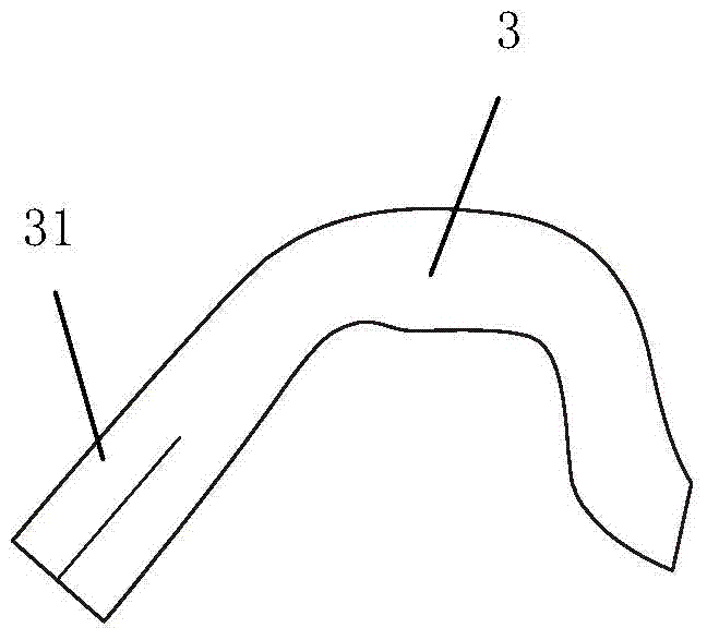
This structure has requirements for the metal pipe at the end 31 of the threading pipe elbow: first, the pipe should be relatively thick, otherwise it will be easily crushed; second, it needs to be molded, and the cost is high; third, it is easy to damage; The tube wall must be relatively thin to form, so the finished product is easily deformed when fastened to the bone, making the threading inaccurate; fifth, due to the thin wall, it is easy to deform after repeated use of the instrument
It can be seen that the structure pressed by the mold: the tube is thick, the wall is thin, the quality is soft, it is difficult to process, and it is easy to deform

Method used


Image

  • An Improved Bone Tunnel Threader Wire Clipping Structure
  • An Improved Bone Tunnel Threader Wire Clipping Structure
  • An Improved Bone Tunnel Threader Wire Clipping Structure

Examples


Embodiment 1

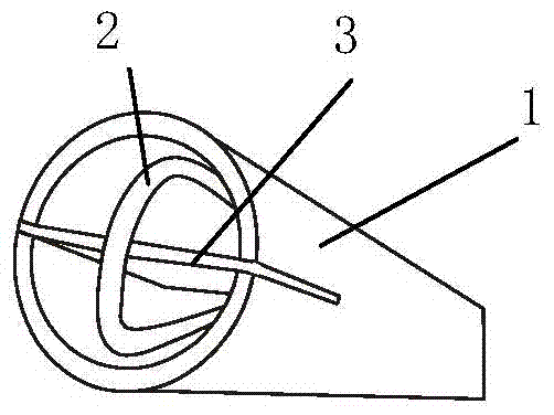
[0027] Such as Figure 3 to Figure 6 As shown, the end 1 of the elbow of the threading pipe in Embodiment 1 is additionally provided with steel wires at both ends of the traveler 2 to facilitate the clamping part of the traveler 2 to clamp the wire. The wall of the part 1 is longitudinally provided with two compartments 11 cut out by laser or molybdenum wire, and the partition 3 is inserted into the two compartments 11 of the elbow end 1 and welded. Of course, the wall at the end of the elbow of the threading pipe can also be provided with only one compartment longitudinally, one side of the partition leans against the inner wall of the elbow end and is welded, and the opposite side is embedded in the compartment at the end of the elbow and welded it is good. The steel wires at both ends of the traveler 2 are respectively arranged on both sides of the partition 3 . It can be seen that the partition plate 3 divides one pipe at the end 1 of the elbow into two pipes, forming a ...

Embodiment 2

[0029] Such as Figure 7 to Figure 11 As shown, the end 1 of the elbow of the threading pipe in the second embodiment is additionally provided with steel wires at both ends of the traveler 2, and the clamping parts that are beneficial to the clamping of the traveler 2 are two branch pipes 4. One branch line pipe 4, half of the pipe wall 41 is removed at the end, the two line branch pipes 4 are arranged back to back longitudinally in the end 1 of the threading pipe elbow, and the steel wires at both ends of the traveler 2 are respectively arranged in the two line branch pipes 4 within. It can be seen that the two back-to-back distribution pipes 4 divide one pipe at the end of the elbow 1 into two pipes, forming a clamping structure.

Embodiment 3

[0031] Such as Figure 12 to Figure 13 As shown, the end 1 of the elbow of the threading pipe in Embodiment 3 is additionally provided with steel wires at both ends of the traveler 2 to facilitate the clamping part of the traveler 2, which consists of a partition 3 and two branch lines Composed of tube 4, the wall of the elbow end 1 of the threading pipe is longitudinally provided with two compartments 11 cut out by laser or molybdenum wire, and the partition 3 is embedded in the two compartments 11 of the elbow end 1 and welded. Of course, the wall at the end of the elbow of the threading pipe can also be provided with only one compartment longitudinally, one side of the partition leans against the inner wall of the elbow end and is welded, and the opposite side is embedded in the compartment at the end of the elbow and welded it is good. The two branch pipes 4 have half of the pipe wall 41 removed from their ends. The two branch pipes 4 are respectively arranged longitudina...


PUM


Abstract

The invention discloses an improved thread clamping structure of a bone tunnel threading device. The improved thread clamping structure comprises a threading tube elbow and a steel wire ring, wherein thread clamping components which separate steel wires at the two ends of the steel wire ring to facilitate thread clamping of the steel wire ring are arranged inside and outside the end of the threading tube elbow. According to the improved thread clamping structure, one tube does not need to be pressed into two tubes to make a thread clamping structure at the end of the elbow, and the thread clamping structure is composed of the thread clamping components instead; the tubes at the end of the elbow do not need to be pressed through a mold, so that the tubes can be made thin and small, and the thinner drilling is, the smaller damage to bones is, and the smaller possibility of mistaken damage to muscular tissue beside the bones is; meanwhile, tube walls can be made thick and hard, so that an instrument is hard and not prone to deformation on the condition that thin tubes are used, and the service life is greatly prolonged; compared with mold pressing, the improved thread clamping structure is easy to process.

Description

technical field [0001] The invention relates to an improved clamping structure of a bone tunnel threader. Background technique [0002] Such as figure 1 As shown, a bone tunnel threader, pushing the ejector rod 1 to the left can drive the ejector rod 2 to retract to the left, when the elbow 3 of the threader is inserted into the bone network, the ejector rod 1 is released, and the spring Under the action, the ejector rod 2 is pushed to the right, so that the ejector rod 2 is pushed against the bone network. At this time, the ejector pin can be used to pass through the ejector rod 2 and the bone network, and the thread can be sent into the steel traveler 5, that is, threading; push the steel wire push rod left and right 4. The traveler 5 on the end face of the elbow 3 can be driven to retract or stretch out. The traveler 5 protrudes to facilitate threading, and the traveler 5 retracts to facilitate clamping the line and withdrawing from the bone. Such as figure 2 As shown...

Claims


Application Information

Patent Timeline
Patent Type & Authority Patents(China)
IPC IPC(8): A61B17/82A61B17/88
CPCA61B17/82A61B17/8861A61B2017/564
Inventor 陈为坚封漭
Owner 广州市丽群医药科技有限公司
Learn More