Secondary gas and liquid mixing pump for nanometer-scale tiny bubble water

A technology of gas-liquid mixing pump and bubble water, which is applied in the direction of mixers, mixing methods, dissolution, etc., can solve the problems that single-stage gas-liquid mixing pumps cannot meet the requirements of gas-liquid mixing effects and fail to achieve nano-scale bubbles, and achieve reasonable Effect of mixing and improving solubility

Active Publication Date: 2016-04-06
北京氢爽生物科技有限公司
View PDF9 Cites 26 Cited by
  • Summary
  • Abstract
  • Description
  • Claims
  • Application Information

AI Technical Summary

Problems solved by technology

[0009] The gas-liquid mixing pumps disclosed above are all single-stage gas-liquid mixing pumps, which can meet the general gas-liquid mixing requirements, but have not yet achieved nano-scale bubble mixing. However, for places with higher requirements for gas-liquid mixing, single-stage gas-liquid mixing The pump cannot meet the demand of gas-liquid mixing effect

Method used


Image

  • Secondary gas and liquid mixing pump for nanometer-scale tiny bubble water
  • Secondary gas and liquid mixing pump for nanometer-scale tiny bubble water
  • Secondary gas and liquid mixing pump for nanometer-scale tiny bubble water

Examples


Embodiment 1

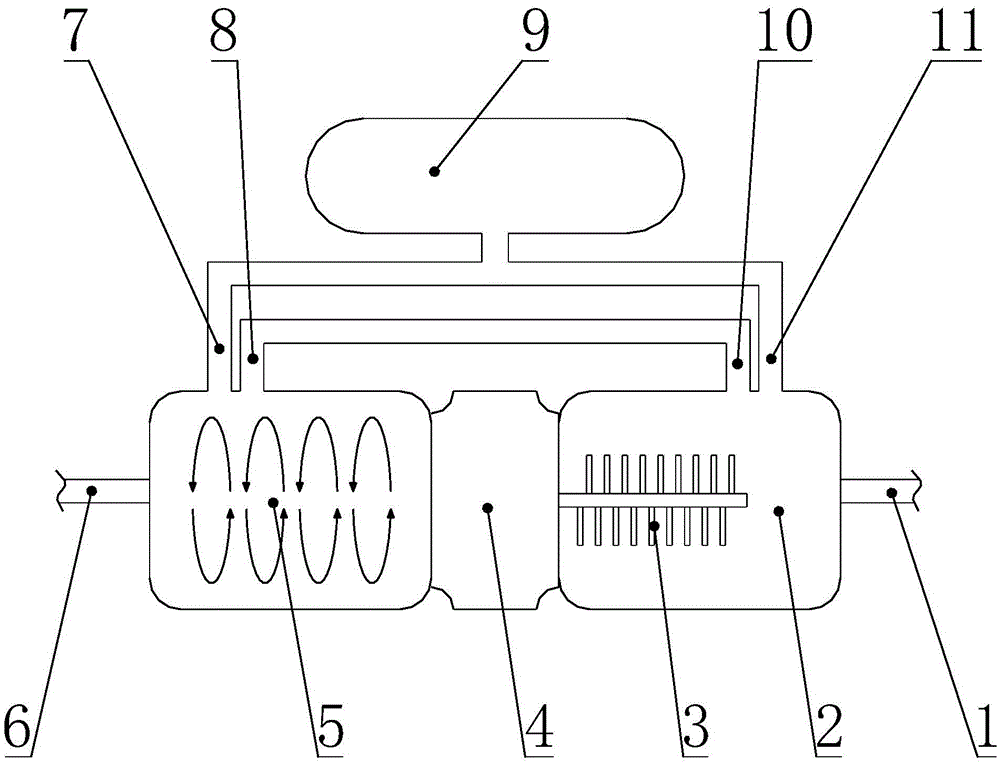
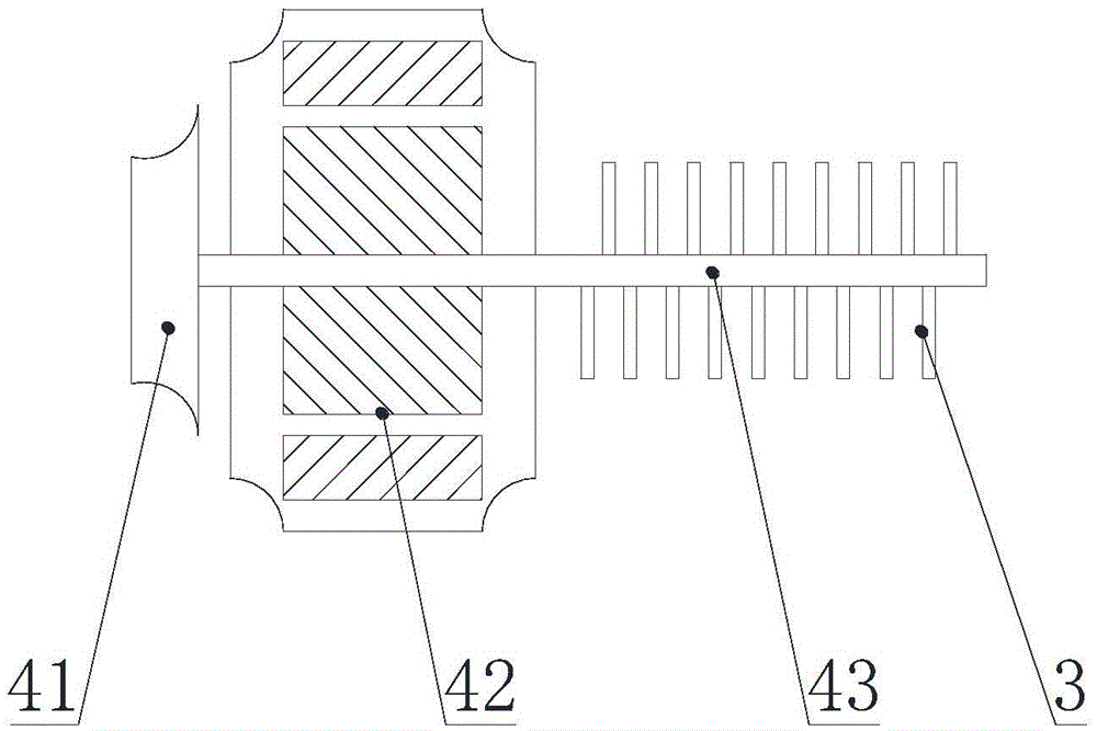
[0032] A two-stage gas-liquid mixing pump for nanoscale micro-bubble water, comprising a stirring mixing chamber 2, a driving device 4, a pneumatic mixing chamber 5 and an air supply device 9, and the stirring mixing chamber 2 and the pneumatic mixing chamber 5 are respectively arranged on the driving device 4, on the side wall of the stirring mixing chamber 2, the first air inlet 11 and the first water outlet 10 are arranged sequentially from top to bottom, and the first water inlet 1 is arranged on the top, and the air pressure mixing chamber 5 The side wall is provided with a second air inlet 7 and a second water inlet 8 sequentially from top to bottom, and the top is provided with a second water outlet 6, and the air supply device 9 is respectively connected to the first air inlet 11 and the second water inlet. The air inlet 7 is connected, and the first water outlet 10 is connected with the second water inlet 8 . The driving device 4 is a motor 42 driven at both ends, the...

Embodiment 2

[0035] Such as Figure 4 As shown, the stirring blades 3 in Embodiment 1 can also be symmetrically arranged or staggeredly arranged, and the purpose is to increase the stirring strength of the gas-liquid mixed water to generate a uniform gas-liquid mixed liquid, and at the same time provide a good balance for the mixed gas-liquid mixture. The liquid provides the power to move downwards, prompting the gas-liquid mixture to flow out through the first water outlet 10 .

Embodiment 3

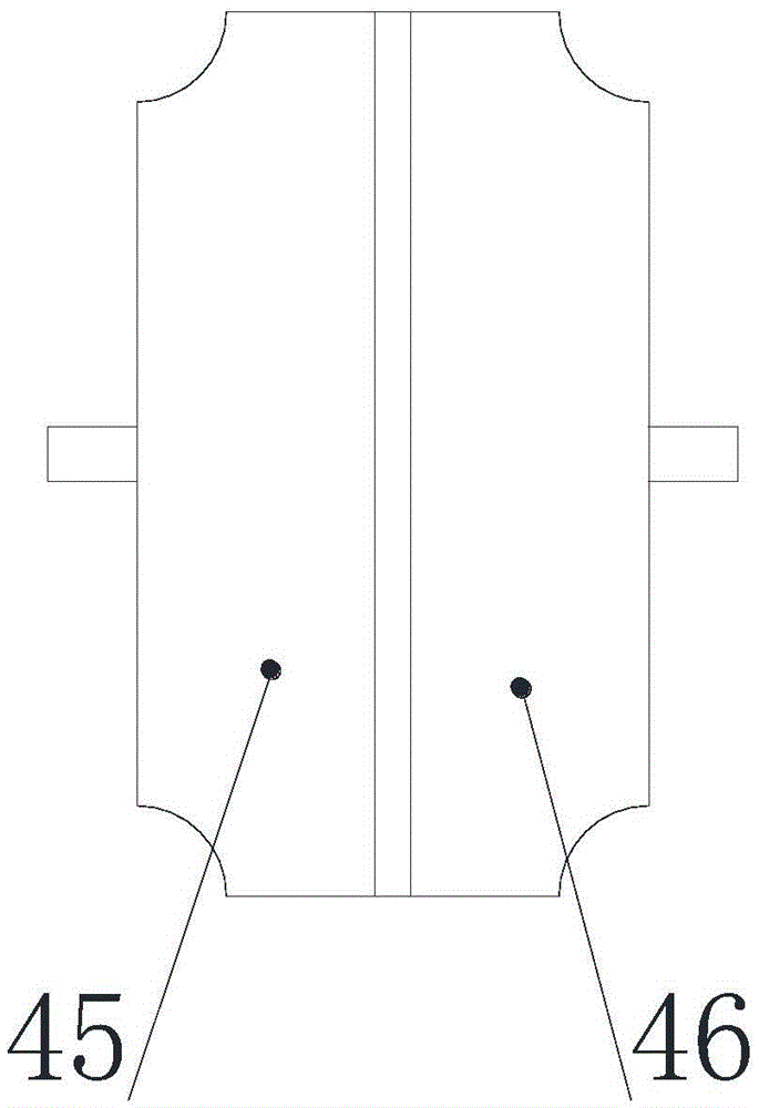
[0037] The driving device 4 in Embodiment 1 can also be a single motor 42 drive system, and the single motor 42 drive system is made up of two first motors 45 and the second motor 46 that are arranged oppositely, and the motor 42 adopts a stepping motor or a servo The motor can control the rotating speed in the stirring mixing chamber 2 and the air pressure mixing chamber 5 respectively, adjust the rotating speed of the stirring blade 3 and the turbine 41 in the stirring mixing chamber 2 and the air pressure mixing chamber 5 according to different requirements, so that the stirring mixing chamber 2 and the air pressure mixing chamber The cavity 5 can form the best speed ratio, improve the quality of gas-liquid mixing, and reduce the energy consumption of the equipment.


PUM


Abstract

The invention discloses a secondary gas and liquid mixing pump for nanometer-scale tiny bubble water. The secondary gas and liquid mixing pump comprises a stirring and mixing cavity, a drive device, an air pressure mixing cavity and a gas supply device. The stirring and mixing cavity and the air pressure mixing cavity are formed in the two sides of the drive device respectively. A first gas inlet and a first water outlet are sequentially formed in the side wall of the stirring and mixing cavity from top to bottom. A first water inlet is formed in the top of the stirring and mixing cavity. A second gas inlet and a second water inlet are sequentially formed in the side wall of the air pressure mixing device from top to bottom, and a second water outlet is formed in the top of the air pressure mixing cavity. The gas supply device is connected with the first gas inlet and the second gas inlet. The first water outlet is connected with the second water inlet. Single-motor middle driving is adopted in the gas-liquid mixing pump, the rotating speed of the stirring and mixing cavity and the rotating speed of the air pressure mixing cavity can be adjusted respectively, the effects of energy-saving operation and step-by-step mixing are achieved, meanwhile, by adopting the two mixing cavities, gas and liquid can be mixed in a layered mode, and the quality of gas and liquid mixing is improved.

Description

technical field [0001] The invention relates to a two-stage gas-liquid mixing pump for nano-scale micro-bubble water. Background technique [0002] Traditional water pumps can only pump water, while traditional air pumps can only compress air, and it has never been possible to add gas to mix and stir while pumping water. How to fully mix the air with the liquid to form a gas-liquid mixed water is an urgent problem to be solved in many industries. [0003] Micro-nano bubble generation technology was produced in the late 1990s and developed vigorously in Japan in the early 21st century. Its manufacturing methods include cyclic shearing, pressurized dissolution, electrochemistry, micropore pressurization, and mixed jets. Micro-nano bubbles can be generated under certain conditions. Usually we call the existence of gas in liquid as bubbles. The formation of bubbles can be encountered in many processes in nature. When the gas is subjected to shear force in the liquid, bubbles ...

Claims


Application Information

Patent Timeline
Patent Type & Authority Applications(China)
IPC IPC(8): B01F13/10B01F3/04
CPCB01F23/23B01F33/823
Inventor 赵江
Owner 北京氢爽生物科技有限公司
Why Eureka
Try Eureka